Cirkit Designer Logo
Cirkit Designer
Your all-in-one circuit design IDE
Home / 
Component Documentation

How to Use m5Dial: Examples, Pinouts, and Specs

Image of m5Dial
Cirkit Designer LogoDesign with m5Dial in Cirkit Designer

Introduction

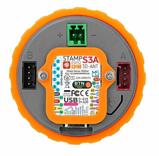
The m5Dial (Manufacturer Part ID: SKU:K130-V11) is a rotary dial component designed by M5Stack. It is a versatile input device that allows users to select values or settings by rotating the dial. The m5Dial is commonly used in electronic projects requiring user input, such as volume control, menu navigation, or parameter adjustments. Its compact design and ease of integration make it a popular choice for hobbyists and professionals alike.

Explore Projects Built with m5Dial

Use Cirkit Designer to design, explore, and prototype these projects online. Some projects support real-time simulation. Click "Open Project" to start designing instantly!
I2C-Controlled OLED Display with External EEPROM and Interactive Pushbuttons
Image of godmode: A project utilizing m5Dial in a practical application
This is a microcontroller-based interactive device featuring a Wemos D1 Mini, an OLED display, external EEPROM, and an I/O expander. It includes user input buttons and status LEDs, with potential MIDI interface capabilities.
Cirkit Designer LogoOpen Project in Cirkit Designer
Arduino Mega 2560 Based Security System with Fingerprint Authentication and SMS Alerts
Image of Door security system: A project utilizing m5Dial in a practical application
This circuit features an Arduino Mega 2560 microcontroller interfaced with a SIM800L GSM module, two fingerprint scanners, an I2C LCD display, an IR sensor, and a piezo buzzer. Power management is handled by a PowerBoost 1000 Basic Pad USB, a TP4056 charging module, and a Li-ion 18650 battery, with an option to use a Mini AC-DC 110V-230V to 5V 700mA module for direct power supply. The primary functionality appears to be a security system with GSM communication capabilities, biometric access control, and visual/audible feedback.
Cirkit Designer LogoOpen Project in Cirkit Designer
I2C LCD and LED Control via BlynkGate with MakerEDU Shield
Image of kxnTest: A project utilizing m5Dial in a practical application
This circuit is designed to interface with Blynk, a platform for controlling Arduino over the internet, and display data on an LCD screen. It includes a MakerEDU Shield connected to two MKE-M01 LED Modules and two MKE-M07 LCD1602 I2C displays for user interaction. The BlynkGate modules are likely used for communication with the Blynk service, and the MTiny Programmer is for programming the microcontrollers. The embedded code suggests that the circuit can receive input via Blynk and display values on the LCDs while also controlling the LEDs.
Cirkit Designer LogoOpen Project in Cirkit Designer
Arduino UNO-Based Smart Display with GSM and Accelerometer
Image of TFT Screen: A project utilizing m5Dial in a practical application
This circuit is a multi-functional system built around an Arduino UNO, featuring an LCD TFT screen for display, a GSM module for communication, an accelerometer for motion sensing, and multiple buzzers for audio alerts. The Arduino UNO interfaces with the LCD screen via SPI, reads accelerometer data through analog inputs, and communicates with the GSM module using digital pins.
Cirkit Designer LogoOpen Project in Cirkit Designer

Explore Projects Built with m5Dial

Use Cirkit Designer to design, explore, and prototype these projects online. Some projects support real-time simulation. Click "Open Project" to start designing instantly!
Image of godmode: A project utilizing m5Dial in a practical application
I2C-Controlled OLED Display with External EEPROM and Interactive Pushbuttons
This is a microcontroller-based interactive device featuring a Wemos D1 Mini, an OLED display, external EEPROM, and an I/O expander. It includes user input buttons and status LEDs, with potential MIDI interface capabilities.
Cirkit Designer LogoOpen Project in Cirkit Designer
Image of Door security system: A project utilizing m5Dial in a practical application
Arduino Mega 2560 Based Security System with Fingerprint Authentication and SMS Alerts
This circuit features an Arduino Mega 2560 microcontroller interfaced with a SIM800L GSM module, two fingerprint scanners, an I2C LCD display, an IR sensor, and a piezo buzzer. Power management is handled by a PowerBoost 1000 Basic Pad USB, a TP4056 charging module, and a Li-ion 18650 battery, with an option to use a Mini AC-DC 110V-230V to 5V 700mA module for direct power supply. The primary functionality appears to be a security system with GSM communication capabilities, biometric access control, and visual/audible feedback.
Cirkit Designer LogoOpen Project in Cirkit Designer
Image of kxnTest: A project utilizing m5Dial in a practical application
I2C LCD and LED Control via BlynkGate with MakerEDU Shield
This circuit is designed to interface with Blynk, a platform for controlling Arduino over the internet, and display data on an LCD screen. It includes a MakerEDU Shield connected to two MKE-M01 LED Modules and two MKE-M07 LCD1602 I2C displays for user interaction. The BlynkGate modules are likely used for communication with the Blynk service, and the MTiny Programmer is for programming the microcontrollers. The embedded code suggests that the circuit can receive input via Blynk and display values on the LCDs while also controlling the LEDs.
Cirkit Designer LogoOpen Project in Cirkit Designer
Image of TFT Screen: A project utilizing m5Dial in a practical application
Arduino UNO-Based Smart Display with GSM and Accelerometer
This circuit is a multi-functional system built around an Arduino UNO, featuring an LCD TFT screen for display, a GSM module for communication, an accelerometer for motion sensing, and multiple buzzers for audio alerts. The Arduino UNO interfaces with the LCD screen via SPI, reads accelerometer data through analog inputs, and communicates with the GSM module using digital pins.
Cirkit Designer LogoOpen Project in Cirkit Designer

Common Applications and Use Cases

  • Volume or brightness control in audio/visual devices
  • Menu navigation in embedded systems
  • Parameter adjustment in industrial or DIY projects
  • User input for IoT devices and smart home systems

Technical Specifications

The m5Dial is equipped with a rotary encoder and additional features to enhance its functionality. Below are the key technical details:

General Specifications

Parameter Value
Manufacturer M5Stack
Part ID SKU:K130-V11
Operating Voltage 3.3V - 5V
Communication Protocol I2C
I2C Address 0x38 (default)
Dimensions 48mm x 48mm x 19mm
Weight 20g

Pin Configuration

The m5Dial uses a Grove connector for easy interfacing. Below is the pin configuration:

Pin Name Description
GND Ground
VCC Power supply (3.3V - 5V)
SCL I2C Clock Line
SDA I2C Data Line

Usage Instructions

The m5Dial is straightforward to use in a circuit, thanks to its I2C communication protocol. Below are the steps to integrate and use the m5Dial in your project:

Connecting the m5Dial

  1. Connect the m5Dial to your microcontroller using a Grove cable.
  2. Ensure the following connections:
    • GND to the ground pin of the microcontroller.
    • VCC to a 3.3V or 5V power source.
    • SCL to the I2C clock pin (e.g., A5 on Arduino UNO).
    • SDA to the I2C data pin (e.g., A4 on Arduino UNO).

Using the m5Dial with Arduino UNO

The m5Dial can be easily interfaced with an Arduino UNO. Below is an example code snippet to read the rotary dial's position:

#include <Wire.h>

// Define the I2C address of the m5Dial
#define M5DIAL_I2C_ADDRESS 0x38

void setup() {
  Wire.begin(); // Initialize I2C communication
  Serial.begin(9600); // Start serial communication for debugging

  // Check if the m5Dial is connected
  Wire.beginTransmission(M5DIAL_I2C_ADDRESS);
  if (Wire.endTransmission() == 0) {
    Serial.println("m5Dial connected successfully!");
  } else {
    Serial.println("Failed to connect to m5Dial. Check connections.");
  }
}

void loop() {
  Wire.beginTransmission(M5DIAL_I2C_ADDRESS);
  Wire.write(0x00); // Command to read the rotary dial position
  Wire.endTransmission();

  Wire.requestFrom(M5DIAL_I2C_ADDRESS, 2); // Request 2 bytes of data
  if (Wire.available() == 2) {
    int position = Wire.read() << 8 | Wire.read(); // Combine two bytes
    Serial.print("Dial Position: ");
    Serial.println(position);
  }

  delay(100); // Small delay to avoid flooding the serial monitor
}

Important Considerations and Best Practices

  • Ensure the I2C address (default: 0x38) does not conflict with other devices on the same bus.
  • Use pull-up resistors on the SDA and SCL lines if your microcontroller does not have internal pull-ups.
  • Avoid excessive force when rotating the dial to prevent mechanical damage.
  • If using multiple m5Dial units, ensure each has a unique I2C address (if supported).

Troubleshooting and FAQs

Common Issues and Solutions

  1. m5Dial not detected on I2C bus:

    • Verify the wiring connections, especially the SDA and SCL lines.
    • Check if the I2C address (0x38) matches the one in your code.
    • Use an I2C scanner sketch to confirm the device's presence.
  2. Incorrect or unstable readings:

    • Ensure a stable power supply (3.3V or 5V).
    • Check for loose connections or damaged cables.
    • Add a small delay in the code to avoid overwhelming the I2C bus.
  3. Physical resistance when rotating the dial:

    • Inspect the dial for debris or mechanical obstructions.
    • Avoid applying excessive force to the dial.

FAQs

Q: Can I use the m5Dial with a Raspberry Pi?
A: Yes, the m5Dial can be used with a Raspberry Pi via the I2C interface. Ensure the I2C pins (SDA and SCL) are correctly connected.

Q: How do I change the I2C address of the m5Dial?
A: The default I2C address is 0x38. Refer to the m5Dial's datasheet or documentation for instructions on changing the address, if supported.

Q: Is the m5Dial compatible with 5V logic?
A: Yes, the m5Dial supports both 3.3V and 5V logic levels, making it compatible with a wide range of microcontrollers.

By following this documentation, you can effectively integrate and use the m5Dial in your electronic projects.