How to Use Adafruit DS2413 1-Wire Two GPIO Controller Breakout: Examples, Pinouts, and Specs
Introduction
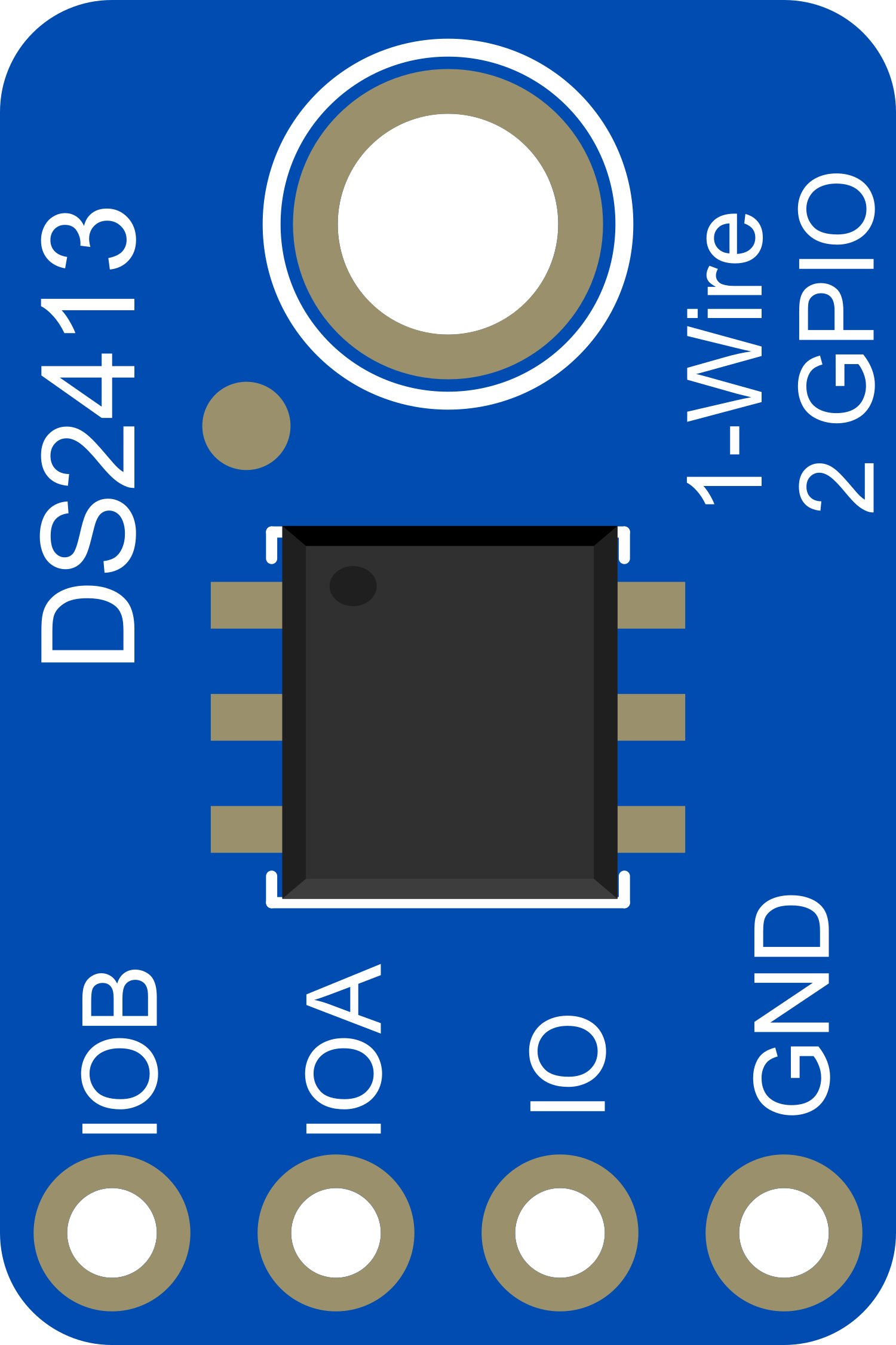
The Adafruit DS2413 1-Wire Two GPIO Controller Breakout is a versatile module that enables control over two digital General Purpose Input/Output (GPIO) pins via the 1-Wire protocol. This protocol allows multiple DS2413 devices to be connected to a single data line for communication with a microcontroller, such as an Arduino UNO, which simplifies wiring in complex projects. Common applications include home automation, industrial control systems, and DIY projects where remote or numerous digital signals need to be managed.
Explore Projects Built with Adafruit DS2413 1-Wire Two GPIO Controller Breakout
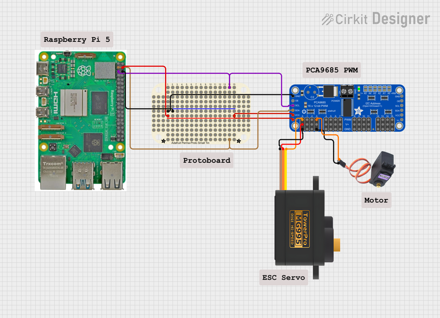

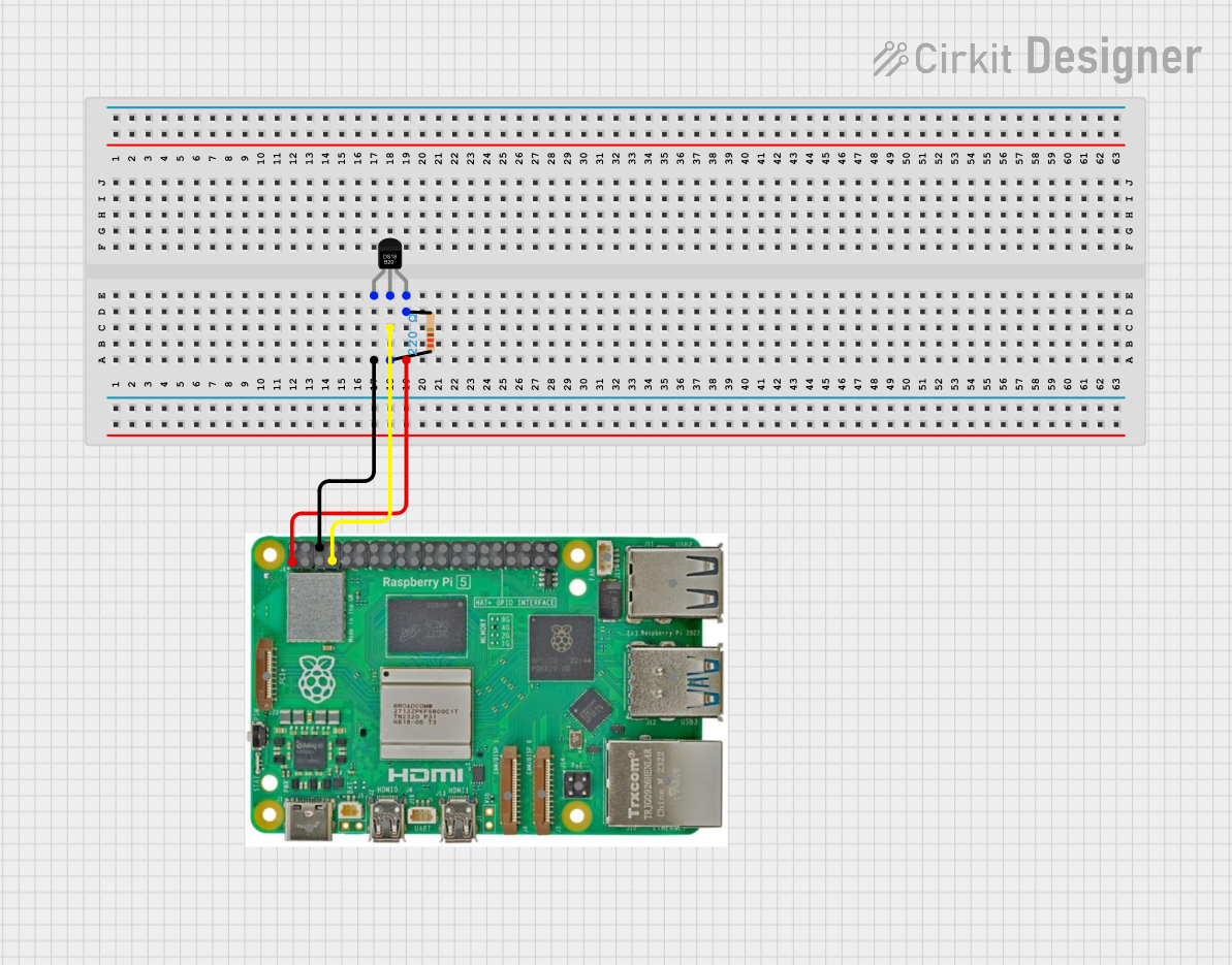

Explore Projects Built with Adafruit DS2413 1-Wire Two GPIO Controller Breakout
Technical Specifications
Key Features
- Communication Protocol: 1-Wire
- GPIO Channels: 2 independently controlled
- Supply Voltage (VDD): 2.8V to 5.25V
- Output Current: 20mA per channel (max)
- Operating Temperature Range: -40°C to +85°C
Pin Configuration and Descriptions
| Pin Number | Name | Description |
|---|---|---|
| 1 | GND | Ground connection |
| 2 | VDD | Supply voltage (2.8V to 5.25V) |
| 3 | DQ | 1-Wire data line |
| 4 | PIOA | GPIO channel A |
| 5 | PIOB | GPIO channel B |
Usage Instructions
Connecting to an Arduino UNO
Power Connections:
- Connect the VDD pin to the 5V output on the Arduino.
- Connect the GND pin to one of the GND pins on the Arduino.
Data Line Connection:
- Connect the DQ pin to a digital I/O pin on the Arduino, for example, pin 2.
External Components:
- Connect external components such as LEDs or relays to PIOA and PIOB pins, ensuring they do not exceed the maximum current rating.
Programming the DS2413
To communicate with the DS2413 using an Arduino, you will need to use a 1-Wire library, such as the OneWire library, and possibly a DS2413-specific library for easier interaction.
Here is a simple example code to control an LED connected to PIOA:
#include <OneWire.h>

// OneWire DS2413 address (replace with your own)
uint8_t ds2413_address[] = { 0x3A, 0x00, 0x00, 0x00, 0x00, 0x00, 0x00, 0x00 };

// Instantiate a OneWire object
OneWire oneWire(2); // Pin 2 connected to DS2413 DQ

void setup() {
  pinMode(LED_BUILTIN, OUTPUT);
  digitalWrite(LED_BUILTIN, HIGH); // Turn on built-in LED to indicate setup is complete
}

void loop() {
  // Code to toggle PIOA would go here
  // This is a placeholder for actual DS2413 library code
}
Important Considerations and Best Practices
- Ensure that the supply voltage does not exceed the maximum rating of 5.25V.
- Use a pull-up resistor (typically 4.7kΩ) on the DQ line for reliable communication.
- Avoid long wire runs to minimize signal degradation, or use a 1-Wire extender if necessary.
- When controlling inductive loads like relays or motors, use appropriate flyback diodes to prevent back EMF damage.
Troubleshooting and FAQs
Common Issues
- No response from the DS2413: Check connections, ensure proper power supply, and verify that the pull-up resistor is in place.
- Intermittent communication: This can be caused by long wires or inadequate pull-up resistance. Shorten the wires or adjust the resistor value.
FAQs
Q: Can I connect multiple DS2413 modules to the same data line? A: Yes, the 1-Wire protocol is designed to handle multiple devices on the same bus. Each device has a unique address.
Q: How do I find the address of my DS2413 module? A: You can use a 1-Wire address finder sketch that searches the bus and prints out the addresses of all connected 1-Wire devices.
Q: What is the maximum distance for the 1-Wire bus? A: The maximum bus length depends on the environment and pull-up resistor value, but it is typically around 100 meters. For longer distances, consider using a 1-Wire extender.
For further assistance, consult the Adafruit DS2413 datasheet and the OneWire library documentation.