Cirkit Designer
Your all-in-one circuit design IDE
Home /
Component Documentation
How to Use 4511: Examples, Pinouts, and Specs

Introduction
The 4511 BCD to 7-segment latch/decoder/driver is an integrated circuit that converts binary-coded decimal (BCD) input data into signals required to drive a 7-segment display. This component is widely used in digital clocks, electronic meters, and other devices that display numerical information.
Explore Projects Built with 4511
Battery-Powered Emergency Alert System with NUCLEO-F072RB, SIM800L, and GPS NEO 6M

This circuit is an emergency alert system that uses a NUCLEO-F072RB microcontroller to send SMS alerts and make calls via a SIM800L GSM module, while obtaining location data from a GPS NEO 6M module. The system is powered by a Li-ion battery and includes a TP4056 module for battery charging and protection, with a rocker switch to control power to the microcontroller.
Arduino 101 Battery-Powered Line Following Robot with IR Sensors and DC Motors
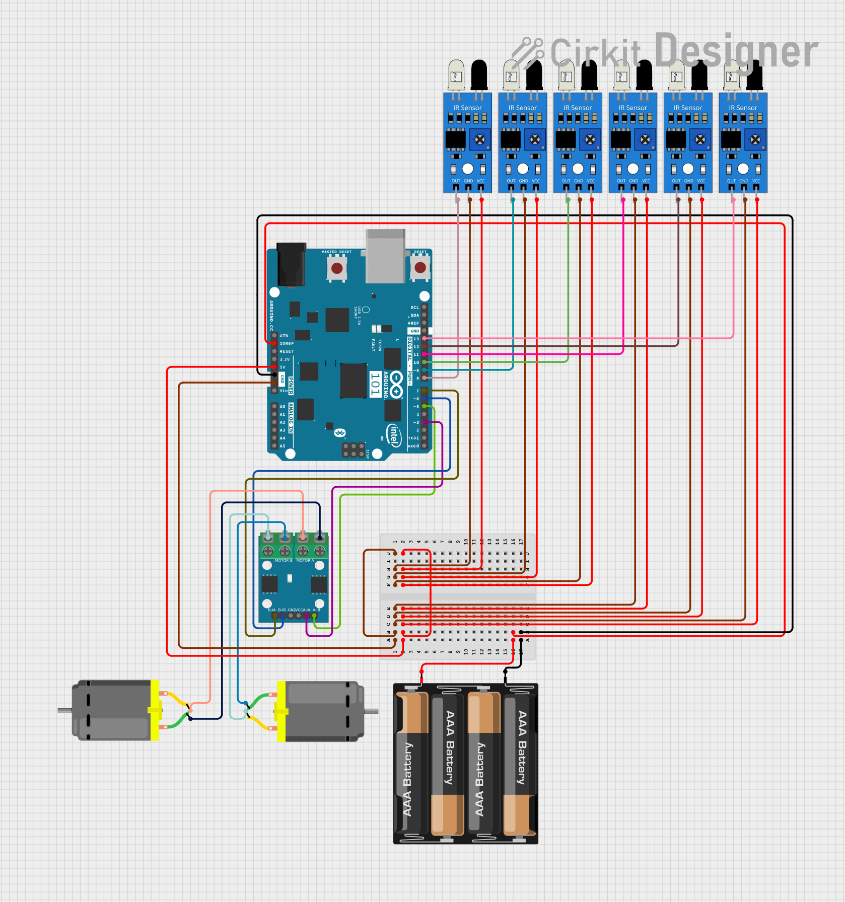
This circuit is a robotic system controlled by an Arduino 101, which uses multiple IR sensors for obstacle detection and an L9110 motor driver to control two DC motors. The power is supplied by a 4 x AAA battery mount, and the IR sensors provide input to the Arduino, which then drives the motors based on the sensor data.
Battery-Powered Arduino Nano with Nokia 5110 LCD and Pushbutton Interface
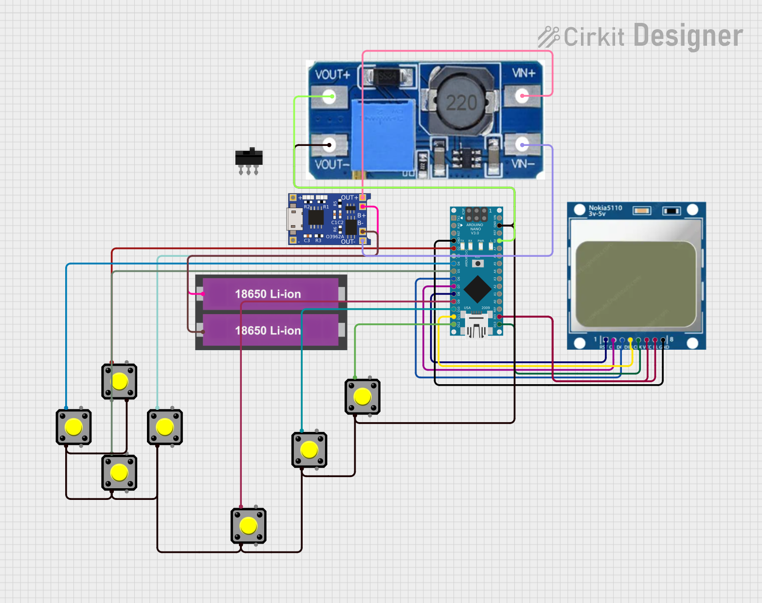
This circuit is a battery-powered system featuring an Arduino Nano that interfaces with a Nokia 5110 LCD and multiple pushbuttons. The TP4056 module charges the 18650 Li-ion batteries, which then power the Arduino through a step-up boost converter. The Arduino controls the LCD display and reads inputs from the pushbuttons for user interaction.
Satellite-Based Timing and Navigation System with SDR and Atomic Clock Synchronization

This circuit appears to be a complex system involving power supply management, GPS and timing synchronization, and data communication. It includes a SI-TEX G1 Satellite Compass for GPS data, an XHTF1021 Atomic Rubidium Clock for precise timing, and Ettus USRP B200 units for software-defined radio communication. Power is supplied through various SMPS units and distributed via terminal blocks and DC jacks. Data communication is facilitated by Beelink MINI S12 N95 computers, RS232 splitters, and a 1000BASE-T Media Converter for network connectivity. RF Directional Couplers are used to interface antennas with the USRP units, and the entire system is likely contained within cases for protection and organization.
Explore Projects Built with 4511
Battery-Powered Emergency Alert System with NUCLEO-F072RB, SIM800L, and GPS NEO 6M
This circuit is an emergency alert system that uses a NUCLEO-F072RB microcontroller to send SMS alerts and make calls via a SIM800L GSM module, while obtaining location data from a GPS NEO 6M module. The system is powered by a Li-ion battery and includes a TP4056 module for battery charging and protection, with a rocker switch to control power to the microcontroller.
Arduino 101 Battery-Powered Line Following Robot with IR Sensors and DC Motors
This circuit is a robotic system controlled by an Arduino 101, which uses multiple IR sensors for obstacle detection and an L9110 motor driver to control two DC motors. The power is supplied by a 4 x AAA battery mount, and the IR sensors provide input to the Arduino, which then drives the motors based on the sensor data.
Battery-Powered Arduino Nano with Nokia 5110 LCD and Pushbutton Interface
This circuit is a battery-powered system featuring an Arduino Nano that interfaces with a Nokia 5110 LCD and multiple pushbuttons. The TP4056 module charges the 18650 Li-ion batteries, which then power the Arduino through a step-up boost converter. The Arduino controls the LCD display and reads inputs from the pushbuttons for user interaction.
Satellite-Based Timing and Navigation System with SDR and Atomic Clock Synchronization
This circuit appears to be a complex system involving power supply management, GPS and timing synchronization, and data communication. It includes a SI-TEX G1 Satellite Compass for GPS data, an XHTF1021 Atomic Rubidium Clock for precise timing, and Ettus USRP B200 units for software-defined radio communication. Power is supplied through various SMPS units and distributed via terminal blocks and DC jacks. Data communication is facilitated by Beelink MINI S12 N95 computers, RS232 splitters, and a 1000BASE-T Media Converter for network connectivity. RF Directional Couplers are used to interface antennas with the USRP units, and the entire system is likely contained within cases for protection and organization.
Common Applications and Use Cases
- Digital clocks and timers
- Electronic counters
- Calculators
- Instrumentation displays
Technical Specifications
Key Technical Details
- Supply Voltage (Vcc): 3V to 18V
- Input Voltage (Vi): -0.5V to Vcc+0.5V
- Output Voltage (Vo): -0.5V to Vcc+0.5V
- Operating Temperature: -55°C to +125°C
- Output Current: 25mA per segment
Pin Configuration and Descriptions
| Pin Number | Name | Description |
|---|---|---|
| 1 | A | BCD input A |
| 2 | B | BCD input B |
| 3 | C | BCD input C |
| 4 | D | BCD input D |
| 5 | LE | Latch Enable |
| 6 | BI | Blanking Input (active low) |
| 7 | LT | Lamp Test (active low) |
| 8 | GND | Ground |
| 9 | a | Segment 'a' output |
| 10 | b | Segment 'b' output |
| 11 | c | Segment 'c' output |
| 12 | d | Segment 'd' output |
| 13 | e | Segment 'e' output |
| 14 | f | Segment 'f' output |
| 15 | g | Segment 'g' output |
| 16 | Vcc | Positive Supply Voltage |
Usage Instructions
How to Use the 4511 in a Circuit
- Connect Vcc to a power supply within the specified range (3V to 18V).
- Connect GND to the ground of the power supply.
- Apply BCD inputs (A, B, C, D) to the corresponding pins.
- Connect the outputs (a-g) to the segments of a 7-segment display with appropriate current-limiting resistors.
- Use the LE pin to latch the input data. When LE is high, the output will follow the input data.
- The BI pin can be used to turn off all segments when pulled low.
- The LT pin can be used to turn on all segments for testing purposes when pulled low.
Important Considerations and Best Practices
- Always use current-limiting resistors with the segment outputs to prevent damage to the IC and the display.
- Avoid applying voltages higher than Vcc+0.5V to the input pins to prevent damage.
- Ensure that unused input pins are tied to an appropriate logic level (high or low).
Troubleshooting and FAQs
Common Issues Users Might Face
- Display not lighting up: Check if the power supply is within the specified range and properly connected to Vcc and GND.
- Incorrect display output: Verify that the BCD inputs are correctly applied and that the LE pin is being used properly.
- Segments are dim: Ensure that the current-limiting resistors are of the correct value for the chosen supply voltage.
Solutions and Tips for Troubleshooting
- Double-check wiring and connections for any loose or incorrect connections.
- Use a multimeter to verify the voltage levels at the power supply and the input pins.
- If a segment is not lighting up, check the corresponding output pin and segment for continuity.
Example Code for Arduino UNO
// Define the pins connected to the 4511 inputs
const int pinA = 2;
const int pinB = 3;
const int pinC = 4;
const int pinD = 5;

void setup() {
  // Set the pins as outputs
  pinMode(pinA, OUTPUT);
  pinMode(pinB, OUTPUT);
  pinMode(pinC, OUTPUT);
  pinMode(pinD, OUTPUT);
}

void loop() {
  // Loop through the digits 0 to 9
  for (int number = 0; number < 10; number++) {
    // Convert the number to BCD and output it
    displayBCD(number);
    delay(1000); // Wait for 1 second
  }
}

void displayBCD(int number) {
  // Use bitwise operations to set the BCD pins
  digitalWrite(pinA, number & 1);
  digitalWrite(pinB, number & 2);
  digitalWrite(pinC, number & 4);
  digitalWrite(pinD, number & 8);
}
This example demonstrates how to cycle through the numbers 0 to 9 on a 7-segment display connected to a 4511 BCD to 7-segment decoder. The displayBCD function takes an integer and sets the appropriate BCD pins on the 4511 to display the corresponding number on the 7-segment display.