
How to Use I2C MOSFET Trailing Edge AC Dimmer: Examples, Pinouts, and Specs
 Design with I2C MOSFET Trailing Edge AC Dimmer in Cirkit Designer
Introduction
The I2C MOSFET Trailing Edge AC Dimmer by KRIDA Electronics is a versatile dimmer circuit designed to control the power delivered to AC loads, such as lights or small appliances. Utilizing MOSFETs for trailing-edge dimming, this component ensures smooth and efficient dimming performance. Its I2C interface allows seamless integration with microcontrollers, making it ideal for remote control and automation applications.
Explore Projects Built with I2C MOSFET Trailing Edge AC Dimmer
 Open Project in Cirkit Designer
 Open Project in Cirkit Designer
 Open Project in Cirkit Designer
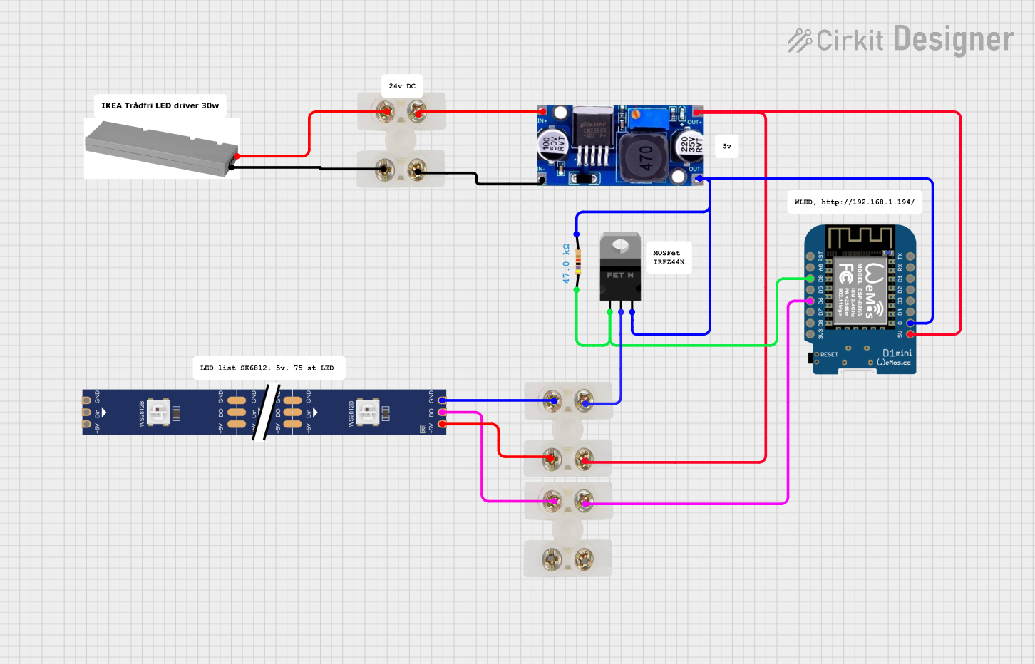 Open Project in Cirkit Designer
Explore Projects Built with I2C MOSFET Trailing Edge AC Dimmer
Open Project in Cirkit DesignerOpen Project in Cirkit DesignerOpen Project in Cirkit DesignerOpen Project in Cirkit DesignerCommon Applications and Use Cases
- Smart home lighting systems
- Automated dimming for energy efficiency
- Remote-controlled AC load management
- Integration with IoT platforms for home automation
- Stage lighting and ambiance control
Technical Specifications
The following table outlines the key technical details of the I2C MOSFET Trailing Edge AC Dimmer:
| Parameter | Value |
|---|---|
| Input Voltage | 85V - 265V AC |
| Output Load Power | Up to 400W |
| Control Interface | I2C (7-bit addressable) |
| Dimming Type | Trailing Edge (MOSFET-based) |
| I2C Voltage Levels | 3.3V or 5V (logic level compatible) |
| Operating Frequency | 50Hz / 60Hz |
| Isolation | Opto-isolated for safety |
| Dimensions | 50mm x 40mm x 20mm |
Pin Configuration and Descriptions
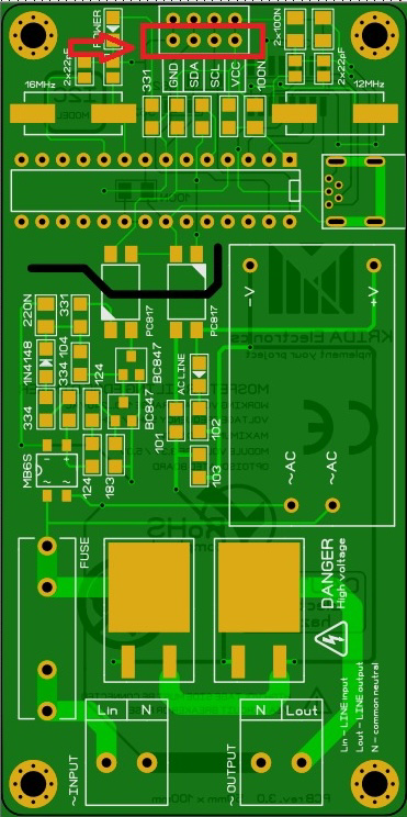
The I2C MOSFET Trailing Edge AC Dimmer has the following pinout:
| Pin Name | Type | Description |
|---|---|---|
| AC_IN | Power Input | Connect to the AC mains input (85V - 265V AC). |
| AC_OUT | Power Output | Connect to the AC load (e.g., light bulb). |
| SDA | I2C Data Line | Serial data line for I2C communication. |
| SCL | I2C Clock Line | Serial clock line for I2C communication. |
| GND | Ground | Common ground for I2C and power. |
| VCC | Power Input | 3.3V or 5V input for I2C logic level. |
Usage Instructions
How to Use the Component in a Circuit
Power Connections:
- Connect the AC mains input to the
AC_INpin. - Connect the load (e.g., light bulb) to the
AC_OUTpin. - Ensure proper isolation and safety precautions when working with AC mains.
- Connect the AC mains input to the
I2C Connections:
- Connect the
SDAandSCLpins to the corresponding I2C pins on your microcontroller. - Connect the
GNDpin to the microcontroller's ground. - Provide 3.3V or 5V to the
VCCpin, depending on your microcontroller's logic level.
- Connect the
Programming:
- Use the I2C address of the dimmer (default:
0x20) to communicate with the device. - Send commands to adjust the dimming level (0-100%).
- Use the I2C address of the dimmer (default:
Safety Considerations:
- Always ensure the circuit is powered off before making connections.
- Use proper insulation and enclosures to prevent accidental contact with live AC components.
Example Code for Arduino UNO
Below is an example Arduino sketch to control the dimmer:
#include <Wire.h> // Include the Wire library for I2C communication

#define DIMMER_I2C_ADDRESS 0x20 // Default I2C address of the dimmer

void setup() {
  Wire.begin(); // Initialize I2C communication
  Serial.begin(9600); // Initialize serial communication for debugging
  Serial.println("I2C MOSFET Dimmer Example");
}

void loop() {
  uint8_t dimmingLevel = 50; // Set dimming level (0-100%)

  // Send dimming level to the dimmer
  Wire.beginTransmission(DIMMER_I2C_ADDRESS);
  Wire.write(dimmingLevel); // Write the dimming level
  Wire.endTransmission();

  Serial.print("Dimming Level Set To: ");
  Serial.println(dimmingLevel);

  delay(1000); // Wait for 1 second before updating again
}
Best Practices
- Use a fuse or circuit breaker for added safety when working with AC mains.
- Avoid exceeding the maximum load power (400W) to prevent damage.
- Ensure proper grounding to avoid electrical noise or interference.
Troubleshooting and FAQs
Common Issues and Solutions
Dimmer Not Responding to I2C Commands:
- Verify the I2C connections (SDA, SCL, GND).
- Check the I2C address of the dimmer. If it has been changed, update the code accordingly.
- Ensure the microcontroller and dimmer share a common ground.
Flickering Lights:
- Ensure the load is compatible with trailing-edge dimming.
- Check for loose connections in the AC circuit.
- Verify that the AC mains voltage is within the specified range (85V - 265V AC).
Overheating:
- Ensure the load does not exceed the maximum power rating (400W).
- Provide adequate ventilation for the dimmer module.
No Output to Load:
- Confirm that the AC mains input is properly connected.
- Check the fuse or circuit breaker in the circuit.
FAQs
Q: Can this dimmer be used with inductive loads like ceiling fans?
A: No, this dimmer is designed for resistive loads (e.g., incandescent or LED lights). Inductive loads may cause malfunction or damage.
Q: How do I change the I2C address of the dimmer?
A: Refer to the manufacturer's documentation for instructions on changing the I2C address. Typically, this involves setting jumpers or sending a specific command.
Q: Is the dimmer compatible with 3.3V microcontrollers like ESP32?
A: Yes, the dimmer supports both 3.3V and 5V logic levels for I2C communication.
Q: Can I use this dimmer for 110V and 220V AC systems?
A: Yes, the dimmer supports a wide input voltage range of 85V - 265V AC, making it compatible with both 110V and 220V systems.
By following this documentation, you can safely and effectively integrate the I2C MOSFET Trailing Edge AC Dimmer into your projects.