How to Use 9 Pin Joystick Port: Examples, Pinouts, and Specs
Documentation for Atari 9-Pin Joystick Port
1. Introduction
The Atari 9-Pin Joystick Port is a widely recognized connector used to interface joystick devices with computers, gaming consoles, and other control systems. Originally introduced by Atari, this connector became a standard for many gaming systems in the 1980s and 1990s. It allows for the transmission of control signals, such as directional inputs and button presses, from the joystick to the host device.
Common Applications and Use Cases:
- Gaming Consoles: Used in classic gaming systems like the Atari 2600, Commodore 64, and Sega Master System.
- Retro Computing: Interfaces with vintage computers for gaming and control applications.
- DIY Projects: Popular among hobbyists for retro gaming emulation, robotics, and custom control systems.
- Arcade Machines: Used in arcade-style joystick setups for gaming cabinets.
2. Technical Specifications
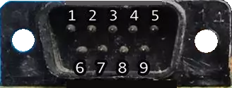
The Atari 9-Pin Joystick Port is a D-subminiature connector with 9 pins arranged in a single row. Each pin is assigned a specific function, such as directional control, button input, or power supply.
Key Technical Details:
| Parameter | Specification |
|---|---|
| Connector Type | 9-pin D-subminiature (DB9) |
| Voltage Rating | 5V DC |
| Current Rating | 10 mA per pin |
| Signal Type | Digital |
| Compatibility | Atari 2600, Commodore 64, Sega Master System, and others |
Pin Configuration and Descriptions:
| Pin Number | Signal Name | Description |
|---|---|---|
| 1 | Up | Activates when the joystick is moved upward. |
| 2 | Down | Activates when the joystick is moved downward. |
| 3 | Left | Activates when the joystick is moved left. |
| 4 | Right | Activates when the joystick is moved right. |
| 5 | Button 1 | Primary action button (e.g., fire button). |
| 6 | +5V | Power supply for the joystick. |
| 7 | Ground | Ground connection. |
| 8 | Button 2 | Secondary action button (optional). |
| 9 | Not Connected | Reserved or unused in most configurations. |
3. Usage Instructions
How to Use the 9-Pin Joystick Port in a Circuit:
Connect the Port to a Host Device:
- Plug the joystick into the 9-pin port on the host device (e.g., gaming console or computer).
- Ensure the connector is securely seated to avoid signal interruptions.
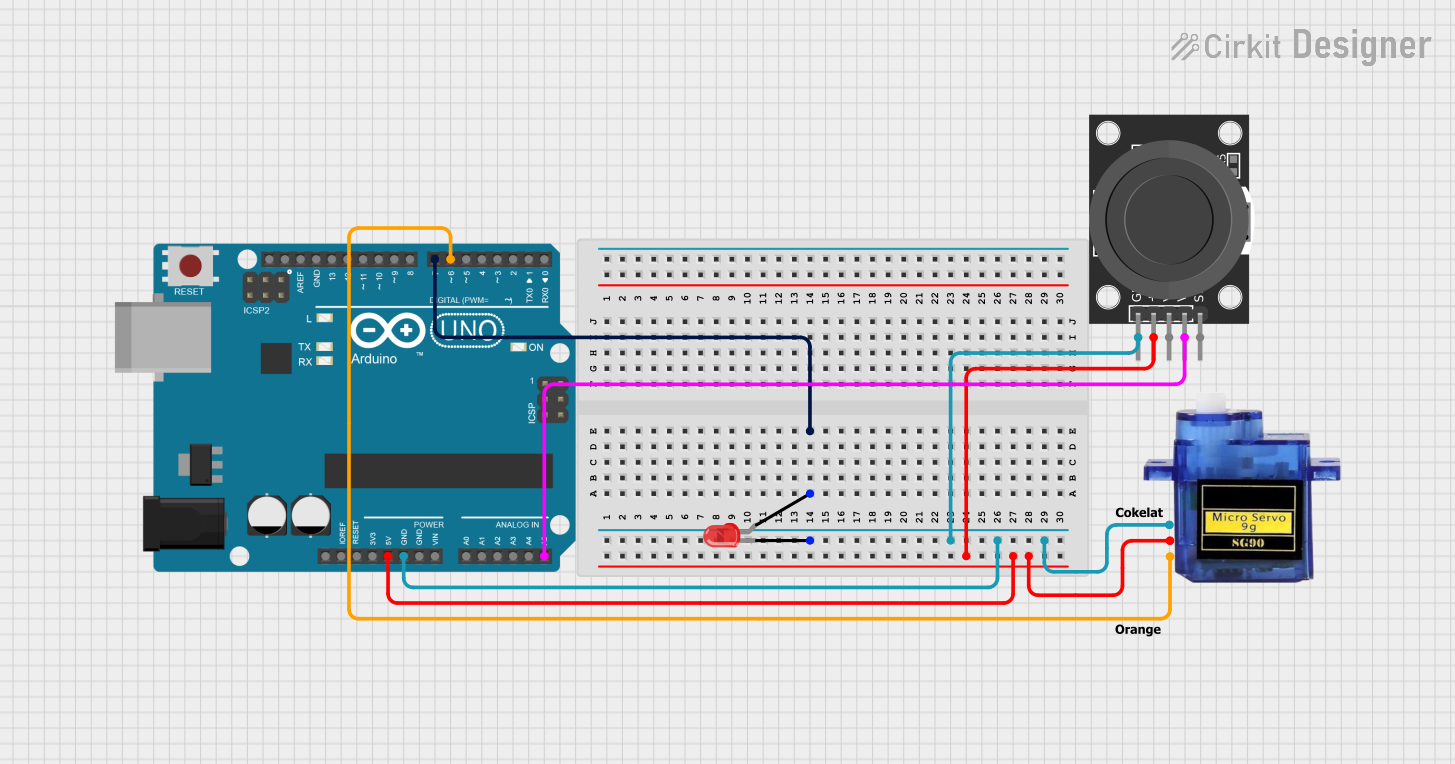
Interface with a Microcontroller (e.g., Arduino UNO):
- Use jumper wires to connect the joystick port pins to the corresponding GPIO pins on the Arduino.
- Provide a 5V power supply to Pin 6 and connect Pin 7 to the Arduino's ground.
Read Inputs:
- Monitor the state of the directional pins (1–4) and button pins (5, 8) using digital input pins on the Arduino.
- When a joystick direction or button is activated, the corresponding pin will be pulled low (logic 0).
Important Considerations and Best Practices:
- Debouncing: Use software debouncing to handle rapid changes in button states.
- Pull-Up Resistors: If the joystick does not include internal pull-up resistors, enable the Arduino's internal pull-ups or add external resistors.
- Voltage Levels: Ensure the joystick operates at 5V logic levels to avoid damaging the microcontroller.
- Pin Protection: Use current-limiting resistors if interfacing with sensitive devices.
4. Example Arduino Code
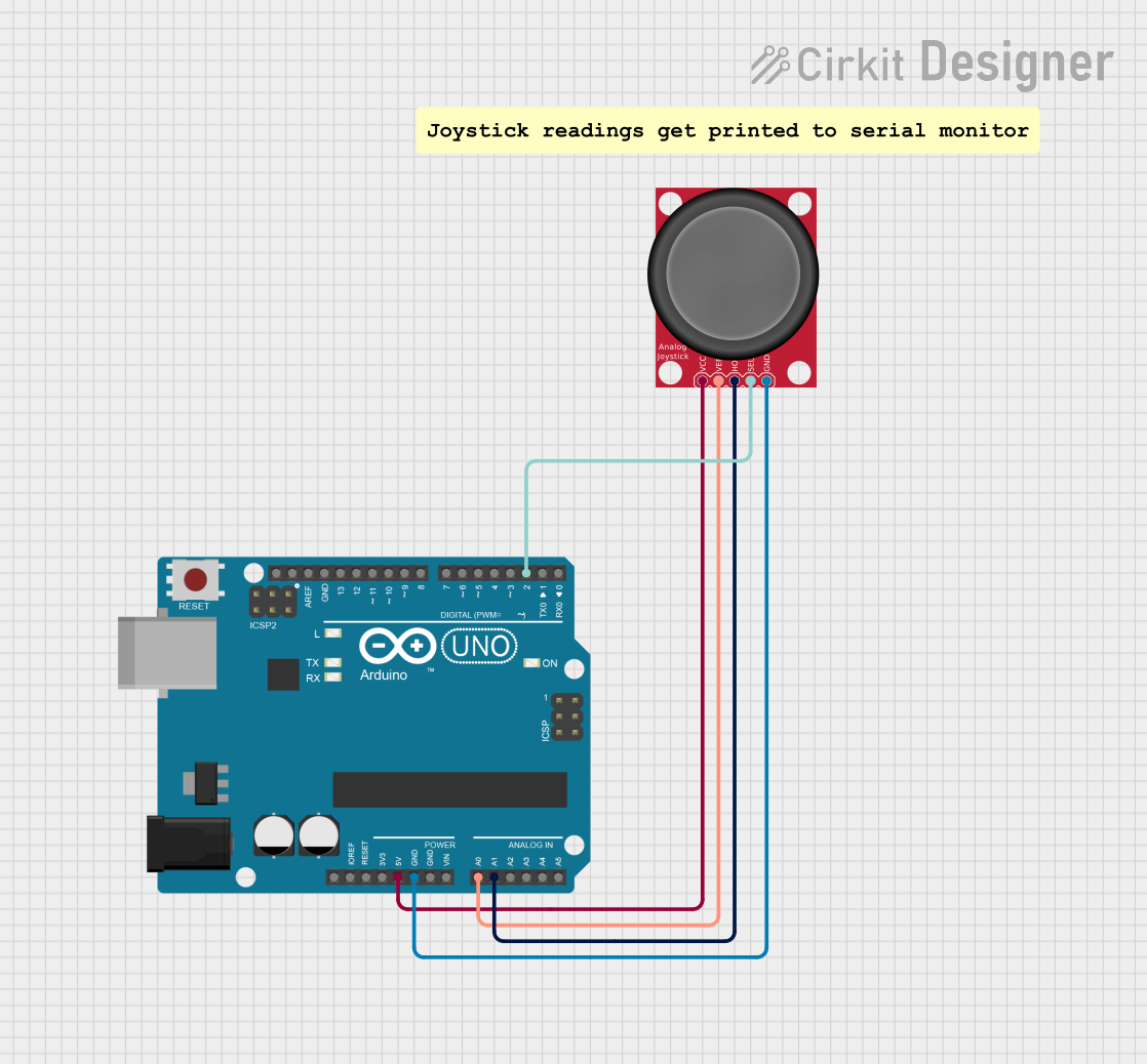
The following example demonstrates how to interface the Atari 9-Pin Joystick Port with an Arduino UNO. The code reads the joystick's directional inputs and button states, then outputs the results to the Serial Monitor.
// Pin assignments for the Atari 9-Pin Joystick Port
const int pinUp = 2;       // Joystick Up (Pin 1)
const int pinDown = 3;     // Joystick Down (Pin 2)
const int pinLeft = 4;     // Joystick Left (Pin 3)
const int pinRight = 5;    // Joystick Right (Pin 4)
const int pinButton1 = 6;  // Button 1 (Pin 5)

// Setup function to initialize pins and Serial Monitor
void setup() {
  // Configure joystick pins as inputs with pull-up resistors
  pinMode(pinUp, INPUT_PULLUP);
  pinMode(pinDown, INPUT_PULLUP);
  pinMode(pinLeft, INPUT_PULLUP);
  pinMode(pinRight, INPUT_PULLUP);
  pinMode(pinButton1, INPUT_PULLUP);

  // Start the Serial Monitor
  Serial.begin(9600);
}

// Main loop to read joystick inputs and print their states
void loop() {
  // Read the state of each joystick pin
  bool upState = digitalRead(pinUp);
  bool downState = digitalRead(pinDown);
  bool leftState = digitalRead(pinLeft);
  bool rightState = digitalRead(pinRight);
  bool button1State = digitalRead(pinButton1);

  // Print the joystick states to the Serial Monitor
  Serial.print("Up: "); Serial.print(!upState); // Inverted logic (LOW = pressed)
  Serial.print(" | Down: "); Serial.print(!downState);
  Serial.print(" | Left: "); Serial.print(!leftState);
  Serial.print(" | Right: "); Serial.print(!rightState);
  Serial.print(" | Button 1: "); Serial.println(!button1State);

  // Add a small delay to avoid flooding the Serial Monitor
  delay(100);
}
5. Troubleshooting and FAQs
Common Issues and Solutions:
Joystick Inputs Not Detected:
- Cause: Loose connection or incorrect wiring.
- Solution: Verify that all connections are secure and match the pin configuration.
Erratic or Unstable Readings:
- Cause: Lack of pull-up resistors or electrical noise.
- Solution: Enable internal pull-up resistors on the Arduino or add external resistors.
Button or Direction Always Reads as Pressed:
- Cause: Short circuit or damaged joystick.
- Solution: Inspect the joystick for physical damage and check for shorts in the wiring.
Joystick Works Intermittently:
- Cause: Faulty connector or worn-out pins.
- Solution: Clean the connector pins and ensure proper alignment.
FAQs:
Q1: Can I use the Atari 9-Pin Joystick Port with modern systems?
A1: Yes, with proper adapters or microcontroller interfaces, the port can be used with modern systems.
Q2: What is the maximum cable length for reliable operation?
A2: For best performance, keep the cable length under 2 meters to minimize signal degradation.
Q3: Can I use this port for custom DIY projects?
A3: Absolutely! The 9-pin joystick port is popular among hobbyists for retro gaming and robotics projects.
This documentation provides a comprehensive guide to understanding, using, and troubleshooting the Atari 9-Pin Joystick Port. Whether you're a retro gaming enthusiast or a DIY hobbyist, this versatile connector is a valuable tool for your projects.
Explore Projects Built with 9 Pin Joystick Port


Explore Projects Built with 9 Pin Joystick Port