How to Use Adafruit ADS1015 12Bit I2C ADC: Examples, Pinouts, and Specs
Introduction
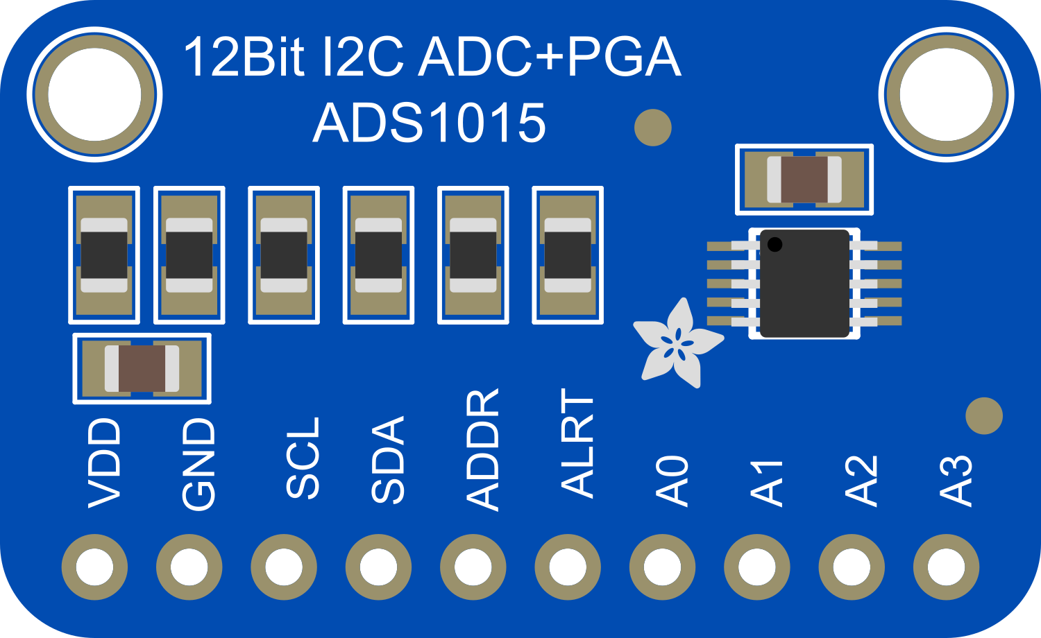
The Adafruit ADS1015 is a precision, low-power, 12-bit analog-to-digital converter (ADC) equipped with an I2C-compatible interface. It offers four multiplexed inputs and can measure signals with a variety of gains, allowing for a range of ±2.048V. This component is ideal for applications requiring accurate analog-to-digital conversion, such as sensor data acquisition, voltage monitoring, and signal analysis. Its small size and ease of use make it suitable for prototyping and integration into existing projects.
Explore Projects Built with Adafruit ADS1015 12Bit I2C ADC


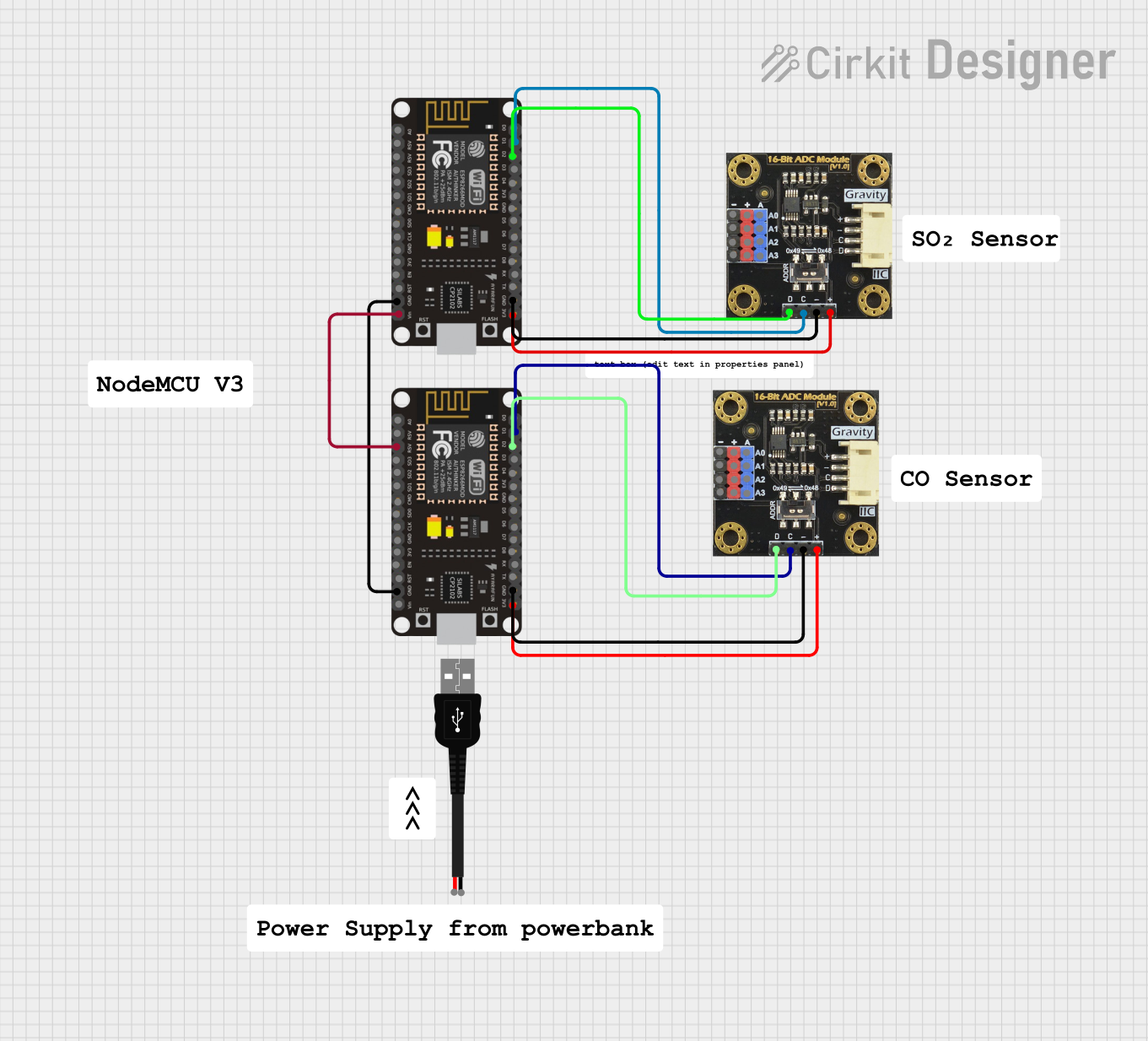
Explore Projects Built with Adafruit ADS1015 12Bit I2C ADC
Technical Specifications
Key Features
- Resolution: 12-bit
- Channels: 4 single-ended or 2 differential inputs
- Programmable Gain Amplifier (PGA): ±2/3, ±1, ±2, ±4, ±8, ±16 V/V
- Data Rate: 128 to 3300 samples per second (SPS)
- Interface: I2C-compatible serial interface
- Supply Voltage: 2.0 to 5.5 V
- Operating Current: 150 µA (typical)
Pin Configuration and Descriptions
| Pin Number | Pin Name | Description |
|---|---|---|
| 1 | VDD | Power supply (2.0V to 5.5V) |
| 2 | GND | Ground connection |
| 3 | SCL | I2C clock input |
| 4 | SDA | I2C data input/output |
| 5 | ADDR | Address pin for I2C address selection |
| 6 | ALERT | Alert/Ready pin (configurable) |
| 7 | A0 | Analog input channel 0 |
| 8 | A1 | Analog input channel 1 |
| 9 | A2 | Analog input channel 2 |
| 10 | A3 | Analog input channel 3 |
Usage Instructions
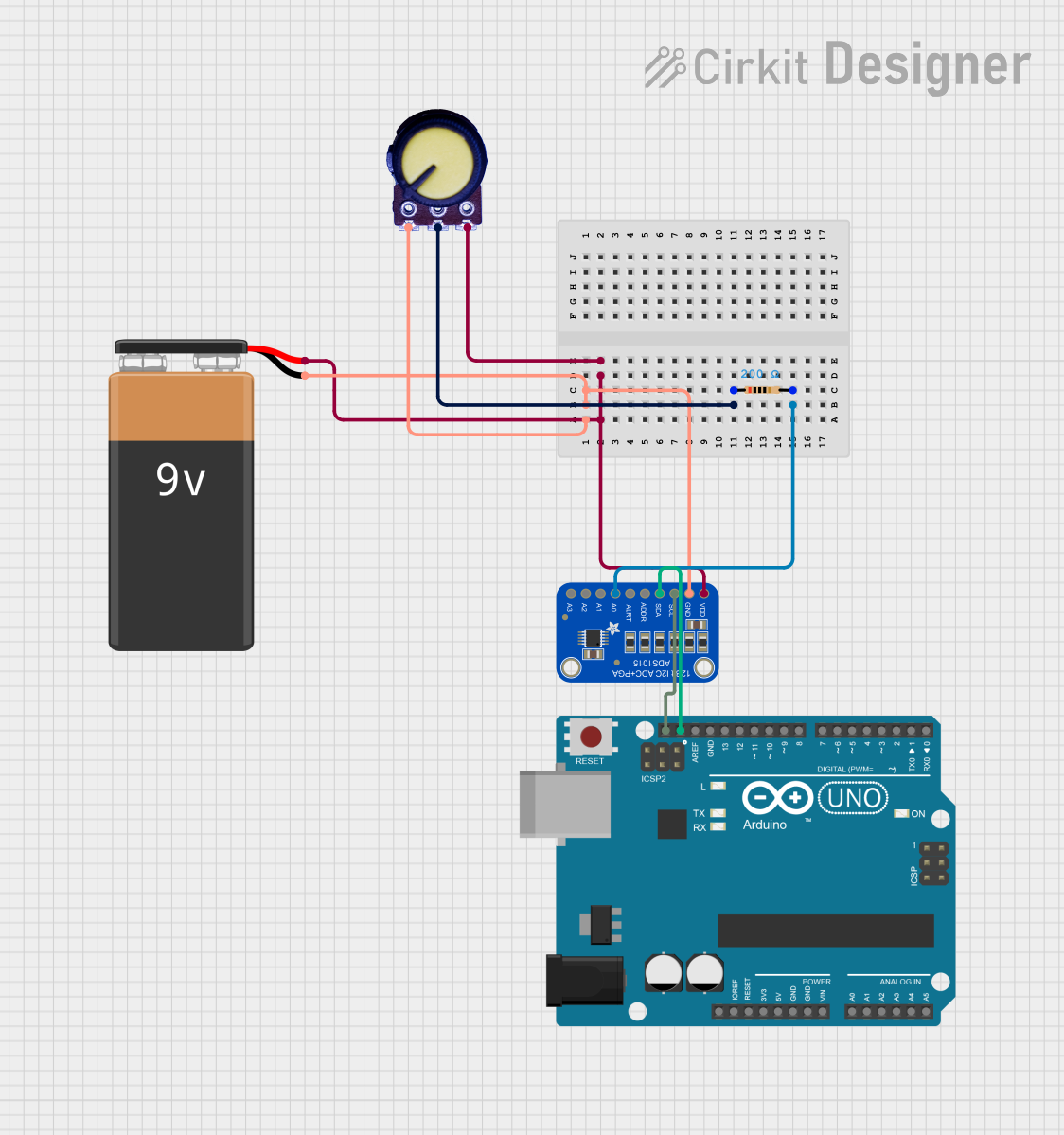
Integration into a Circuit
- Connect VDD to a 2.0V to 5.5V power supply.
- Connect GND to the system ground.
- Connect SCL and SDA to the I2C clock and data lines, respectively.
- Set the ADDR pin to the appropriate logic level to determine the I2C address.
- Connect the analog input(s) to A0-A3 as required for your application.
- Optionally, use the ALERT pin for conversion ready or threshold alert functions.
Best Practices
- Use pull-up resistors on the SCL and SDA lines as required by the I2C protocol.
- Keep analog signal paths as short as possible to minimize noise.
- Decouple the power supply with a 0.1 µF capacitor close to the VDD pin.
- Configure the ADS1015's registers according to your application's requirements.
Example Code for Arduino UNO
#include <Wire.h>
#include <Adafruit_ADS1015.h>

Adafruit_ADS1115 ads;  // Use this for the 16-bit version

void setup(void) {
  Serial.begin(9600);
  ads.begin();  // Initialize the ADS1015
}

void loop(void) {
  int16_t adc0, adc1, adc2, adc3;

  // Read all four channels and print them out
  adc0 = ads.readADC_SingleEnded(0);
  adc1 = ads.readADC_SingleEnded(1);
  adc2 = ads.readADC_SingleEnded(2);
  adc3 = ads.readADC_SingleEnded(3);
  Serial.print("AIN0: "); Serial.println(adc0);
  Serial.print("AIN1: "); Serial.println(adc1);
  Serial.print("AIN2: "); Serial.println(adc2);
  Serial.print("AIN3: "); Serial.println(adc3);
  Serial.println(" ");

  delay(1000);  // Pause for a second
}
Troubleshooting and FAQs
Common Issues
- No response from the device: Ensure that the I2C address is correctly set and that the SCL and SDA lines are properly connected with pull-up resistors.
- Inaccurate readings: Check that the input voltage is within the specified range and that the PGA gain is correctly configured.
- Noisy signal: Ensure that the analog input lines are kept short and away from high-frequency signals.
FAQs
Q: How do I change the I2C address of the ADS1015? A: The I2C address can be changed by connecting the ADDR pin to GND, VDD, SDA, or SCL, resulting in four possible addresses.
Q: Can the ADS1015 be used with a 3.3V system? A: Yes, the ADS1015 can operate at voltages between 2.0V and 5.5V, making it compatible with both 3.3V and 5V systems.
Q: How can I increase the resolution of my measurements? A: The ADS1015 is a 12-bit ADC, so the resolution is fixed. However, you can increase the effective resolution by using the programmable gain amplifier (PGA) to match the input signal range.
Q: What is the purpose of the ALERT pin? A: The ALERT pin can be configured to act as a conversion ready signal or as an alert when the analog input exceeds a programmed threshold.
This documentation provides a comprehensive guide to using the Adafruit ADS1015 12-Bit I2C ADC with an Arduino UNO. For further information, consult the datasheet and additional resources provided by Adafruit.