How to Use OBD-II UART Adapter: Examples, Pinouts, and Specs
Introduction
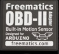
The OBD-II UART Adapter by Freematics is a versatile device designed to interface with a vehicle's On-Board Diagnostics (OBD-II) system. It connects to the OBD-II port of a vehicle and communicates with the onboard diagnostics system via a UART (Universal Asynchronous Receiver-Transmitter) interface. This adapter enables users to retrieve real-time vehicle data, perform diagnostics, and monitor performance metrics.
Explore Projects Built with OBD-II UART Adapter
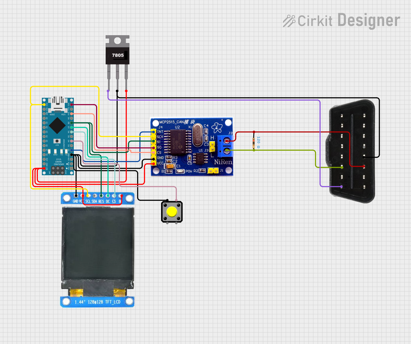
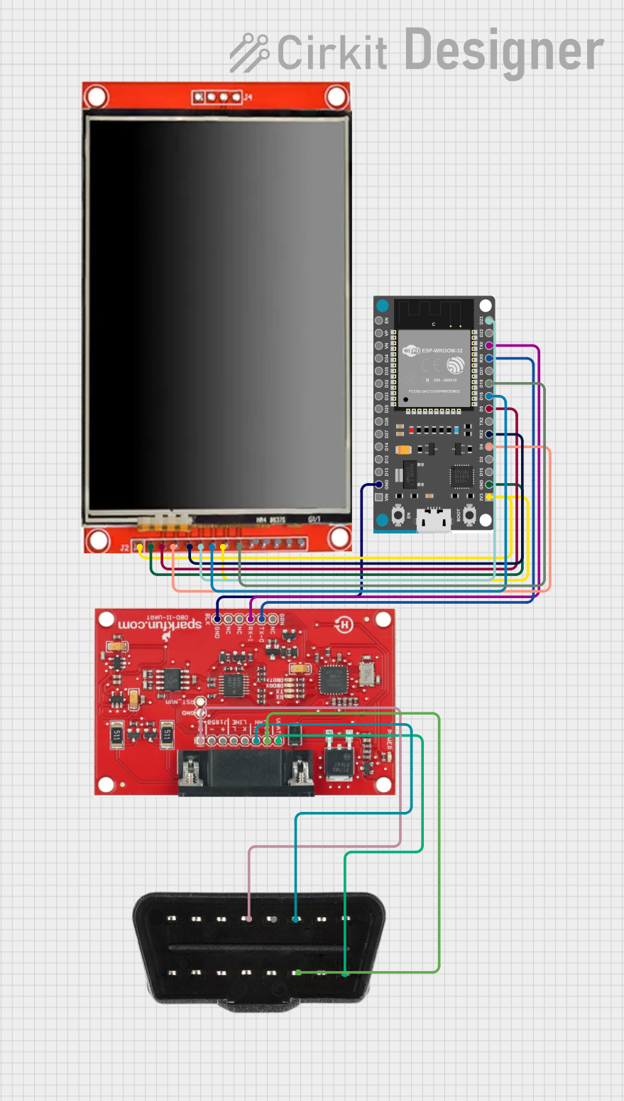


Explore Projects Built with OBD-II UART Adapter
Common Applications and Use Cases
- Vehicle diagnostics and troubleshooting
- Real-time data logging for performance analysis
- Integration with microcontrollers (e.g., Arduino) for custom automotive projects
- Fleet management and telematics systems
- Educational purposes for learning about vehicle communication protocols
Technical Specifications
The following table outlines the key technical details of the Freematics OBD-II UART Adapter:
| Specification | Details |
|---|---|
| Input Voltage | 9V to 16V (powered via the OBD-II port) |
| Communication Interface | UART (3.3V logic level) |
| Supported Protocols | ISO 15765-4 (CAN), ISO 14230-4 (KWP2000), ISO 9141-2, SAE J1850 PWM/VPW |
| Baud Rate | Configurable (default: 9600 bps) |
| Operating Temperature | -40°C to 85°C |
| Dimensions | 48mm x 25mm x 15mm |
Pin Configuration and Descriptions
The adapter features a UART interface for communication. Below is the pinout for the UART connector:
| Pin | Name | Description |
|---|---|---|
| 1 | VCC | Power input for the UART interface (3.3V or 5V, depending on the microcontroller) |
| 2 | GND | Ground connection |
| 3 | TXD | Transmit data (output from the adapter) |
| 4 | RXD | Receive data (input to the adapter) |
Usage Instructions
How to Use the OBD-II UART Adapter in a Circuit
- Connect the Adapter to the Vehicle:
- Plug the OBD-II UART Adapter into the vehicle's OBD-II port, typically located under the dashboard.
- Connect to a Microcontroller:
- Use the UART interface to connect the adapter to a microcontroller (e.g., Arduino UNO). Ensure proper voltage levels (3.3V or 5V) for the UART pins.
- Power the Adapter:
- The adapter is powered directly from the vehicle's OBD-II port. No external power supply is required.
- Configure Communication:
- Set the UART baud rate on the microcontroller to match the adapter's default (9600 bps) or a custom baud rate if configured.
Important Considerations and Best Practices
- Ensure the vehicle's ignition is turned on to allow the OBD-II system to communicate.
- Use a level shifter if your microcontroller operates at 5V logic levels, as the adapter uses 3.3V logic.
- Avoid prolonged connections to prevent draining the vehicle's battery.
- Verify the supported OBD-II protocol of your vehicle to ensure compatibility.
Example Code for Arduino UNO
Below is an example Arduino sketch to retrieve and display vehicle speed using the OBD-II UART Adapter:
#include <SoftwareSerial.h>

// Define RX and TX pins for SoftwareSerial
SoftwareSerial obdSerial(10, 11); // RX = pin 10, TX = pin 11

void setup() {
  Serial.begin(9600); // Initialize Serial Monitor
  obdSerial.begin(9600); // Initialize OBD-II UART communication

  // Send initialization command to the OBD-II adapter
  obdSerial.println("ATZ"); // Reset the adapter
  delay(1000); // Wait for the adapter to reset

  // Set the protocol to automatic
  obdSerial.println("ATSP0");
  delay(1000);

  Serial.println("OBD-II Adapter Initialized");
}

void loop() {
  // Request vehicle speed (PID 0D)
  obdSerial.println("010D");
  delay(100); // Wait for the response

  // Read the response from the adapter
  while (obdSerial.available()) {
    char c = obdSerial.read();
    Serial.print(c); // Print the response to the Serial Monitor
  }
  delay(1000); // Wait before sending the next request
}
Notes:
- Replace
10and11with the appropriate pins if using different connections. - Ensure the vehicle supports the requested PID (e.g., 0D for speed).
Troubleshooting and FAQs
Common Issues and Solutions
No Response from the Adapter:
- Ensure the vehicle's ignition is turned on.
- Verify the UART connections (TX, RX, VCC, GND) are correct.
- Check the baud rate configuration on the microcontroller.
Incorrect or Garbled Data:
- Confirm the UART voltage levels match between the adapter and the microcontroller.
- Ensure the OBD-II protocol is supported by the vehicle.
Adapter Not Powering On:
- Check the OBD-II port for proper power output (typically 12V).
- Inspect the adapter for physical damage or loose connections.
FAQs
Q: Can this adapter work with all vehicles?
A: The adapter supports most vehicles manufactured after 1996 that comply with OBD-II standards. However, compatibility depends on the specific protocol used by the vehicle.
Q: How do I change the baud rate of the adapter?
A: Use the ATBRx command, where x specifies the desired baud rate. Refer to the Freematics user manual for details.
Q: Can I use this adapter with a Raspberry Pi?
A: Yes, the adapter can be connected to a Raspberry Pi via its UART interface. Ensure proper voltage level conversion if needed.
Q: Is it safe to leave the adapter connected to the vehicle?
A: While the adapter has low power consumption, it is recommended to disconnect it when the vehicle is not in use to prevent battery drain.