
How to Use V_REG_MIC5235: Examples, Pinouts, and Specs

 Design with V_REG_MIC5235 in Cirkit Designer
Introduction
The MIC5235 is a low-dropout (LDO) voltage regulator designed to provide a stable output voltage with minimal quiescent current. It is particularly well-suited for battery-powered applications due to its low power consumption and ability to deliver up to 150 mA of output current. The MIC5235 features a wide input voltage range, excellent line and load regulation, and is available in compact packaging, making it ideal for portable and space-constrained designs.
Explore Projects Built with V_REG_MIC5235
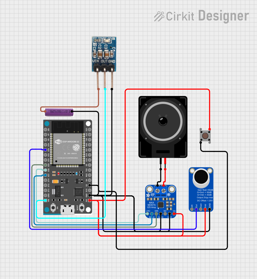 Open Project in Cirkit Designer
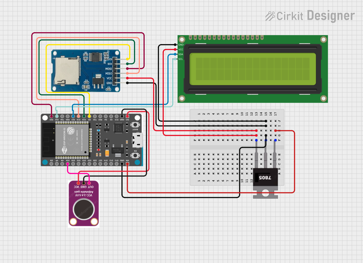 Open Project in Cirkit Designer
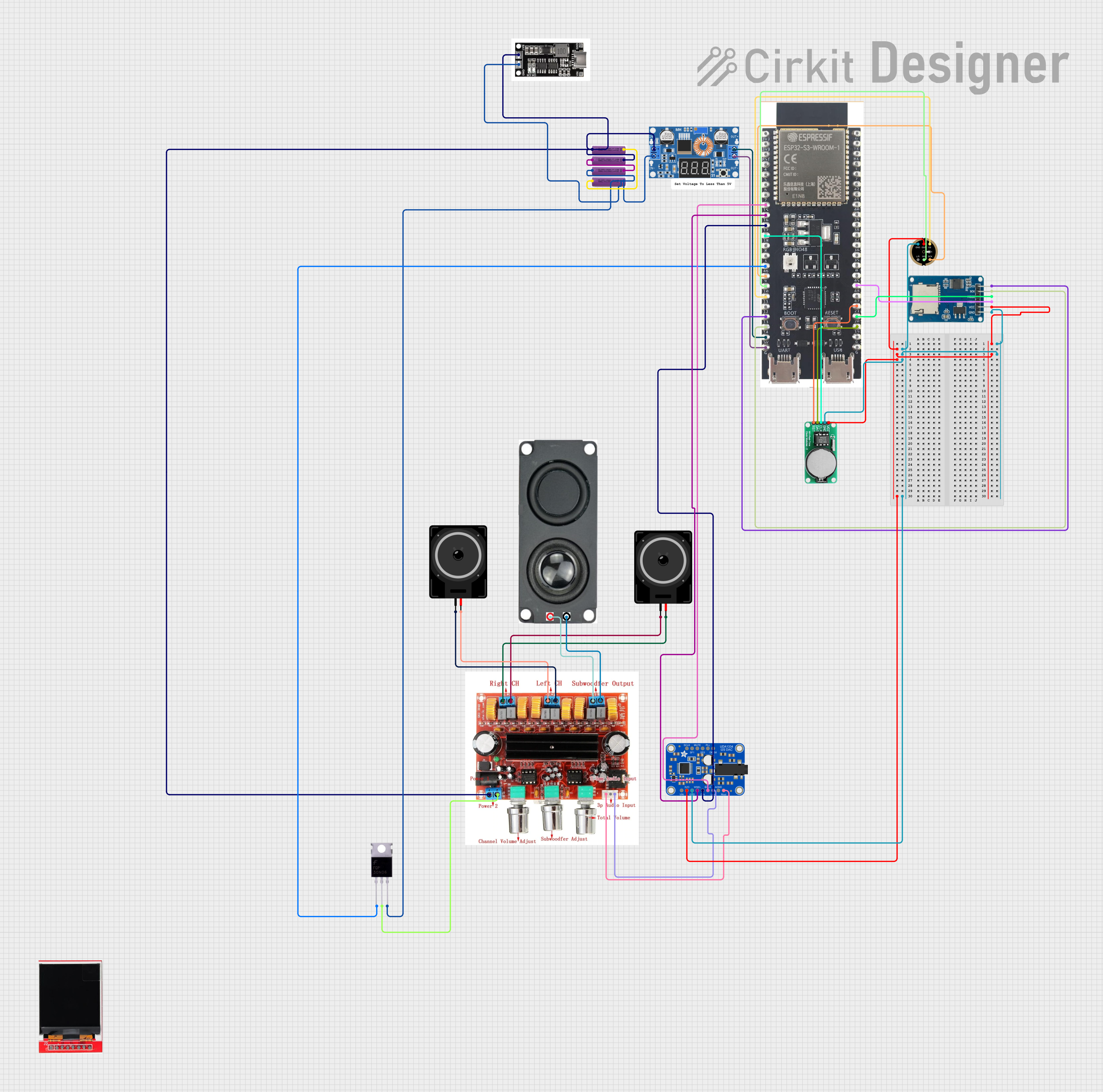 Open Project in Cirkit Designer
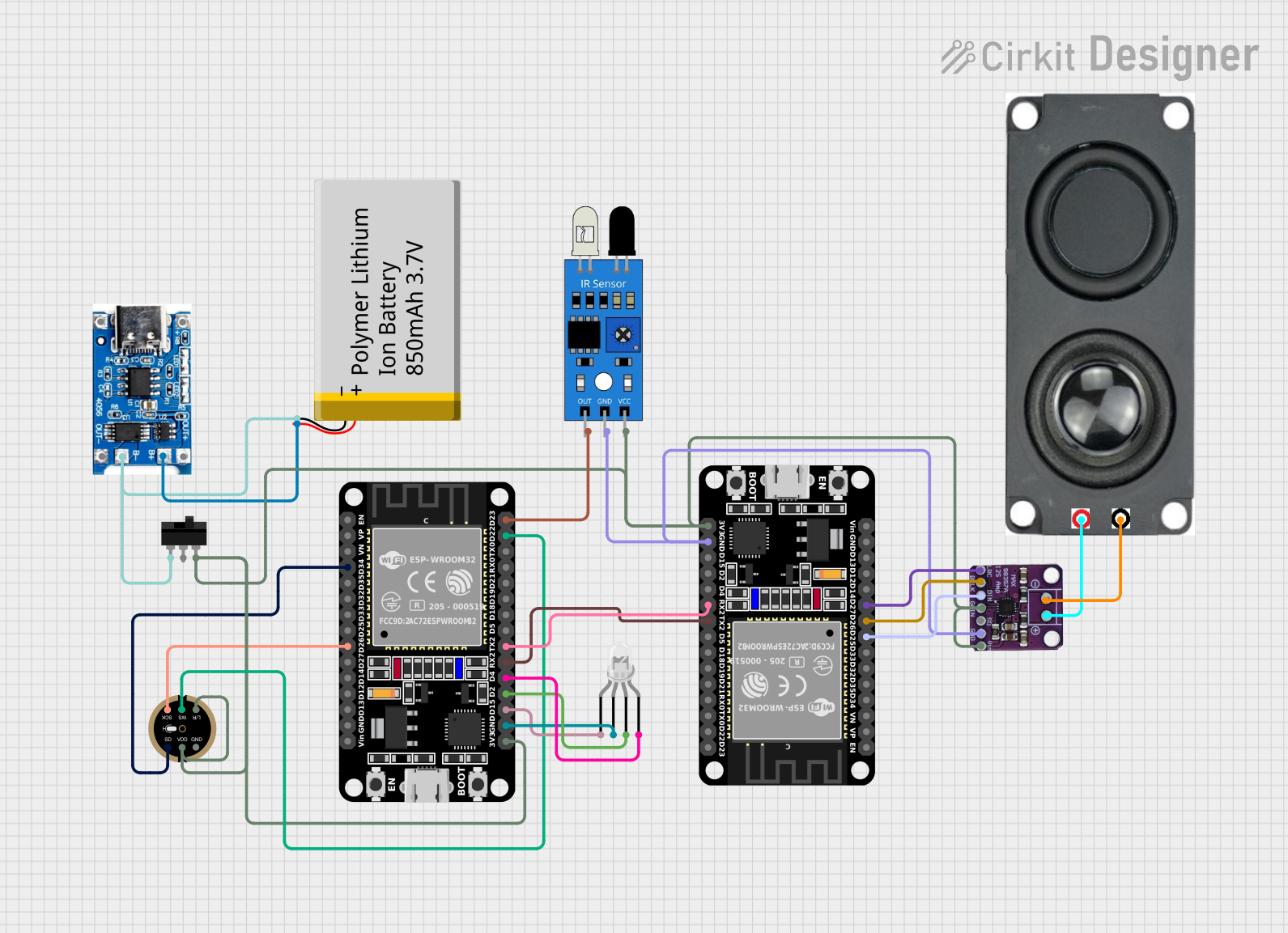 Open Project in Cirkit Designer
Explore Projects Built with V_REG_MIC5235
Open Project in Cirkit DesignerOpen Project in Cirkit DesignerOpen Project in Cirkit DesignerOpen Project in Cirkit DesignerCommon Applications
- Battery-powered devices (e.g., wearables, IoT sensors)
- Portable electronics
- Microcontroller power supplies
- Low-noise analog circuits
- Post-regulation for switching power supplies
Technical Specifications
Key Specifications
| Parameter | Value |
|---|---|
| Input Voltage Range | 2.3 V to 24 V |
| Output Voltage Range | 1.24 V to 20 V (adjustable) |
| Maximum Output Current | 150 mA |
| Dropout Voltage | 300 mV @ 150 mA (typical) |
| Quiescent Current | 18 µA (typical) |
| PSRR (Power Supply Rejection Ratio) | 60 dB @ 1 kHz (typical) |
| Operating Temperature Range | -40°C to +125°C |
| Package Options | SOT-23-5, TSOT-23-5 |
Pin Configuration and Descriptions
SOT-23-5 / TSOT-23-5 Package
| Pin Number | Name | Description |
|---|---|---|
| 1 | VIN | Input voltage. Connect to the power source (2.3 V to 24 V). |
| 2 | GND | Ground. Connect to the system ground. |
| 3 | EN | Enable pin. Drive high to enable the regulator; drive low to disable it. |
| 4 | ADJ | Adjust pin. Connect to a resistor divider to set the output voltage. |
| 5 | VOUT | Regulated output voltage. Connect to the load. |
Usage Instructions
Using the MIC5235 in a Circuit
Input Capacitor (CIN):
Place a ceramic capacitor (1 µF or higher) close to the VIN pin to stabilize the input voltage and reduce noise.Output Capacitor (COUT):
Use a low-ESR ceramic capacitor (1 µF or higher) at the VOUT pin to ensure stable operation and minimize output voltage ripple.Setting the Output Voltage:
The output voltage is adjustable using an external resistor divider connected to the ADJ pin. The output voltage can be calculated using the formula:
[ V_{OUT} = V_{REF} \times \left(1 + \frac{R1}{R2}\right) ]
Where ( V_{REF} ) is 1.24 V (reference voltage), and ( R1 ) and ( R2 ) are the resistors in the divider network.Enable/Disable Functionality:
The EN pin allows the regulator to be turned on or off. Drive the EN pin high (above 1.6 V) to enable the regulator, or low (below 0.4 V) to disable it.Thermal Considerations:
Ensure adequate heat dissipation by using proper PCB layout techniques. Avoid placing the MIC5235 near heat-generating components.
Example Circuit
Below is an example of how to use the MIC5235 to regulate a 5 V input to a 3.3 V output:
VIN (5V) ----+---- CIN (1 µF) ---- VIN (MIC5235)
             |
            GND

VOUT (MIC5235) ---- COUT (1 µF) ---- VOUT (3.3V)
             |
            GND

EN (MIC5235) ---- Pull-up resistor (10 kΩ to VIN)
ADJ (MIC5235) ---- Resistor divider (R1, R2) to set VOUT
Using MIC5235 with Arduino UNO
The MIC5235 can be used to power an Arduino UNO or other microcontrollers. Below is an example of Arduino code to control the EN pin:
// Define the pin connected to the EN pin of MIC5235
const int enablePin = 7;

void setup() {
  // Set the enable pin as an output
  pinMode(enablePin, OUTPUT);

  // Enable the MIC5235 by setting the pin HIGH
  digitalWrite(enablePin, HIGH);
}

void loop() {
  // Keep the regulator enabled
  delay(1000);

  // Optionally, disable the regulator for power saving
  // Uncomment the following lines to test disabling
  // digitalWrite(enablePin, LOW);
  // delay(1000);
}
Best Practices
- Always use low-ESR capacitors for CIN and COUT to ensure stability.
- Keep the input and output capacitors as close as possible to the MIC5235 pins.
- Use proper resistor values for the voltage divider to minimize noise and power loss.
- Avoid exceeding the maximum input voltage or output current ratings.
Troubleshooting and FAQs
Common Issues and Solutions
Output Voltage is Unstable or Incorrect:
- Ensure that the input and output capacitors meet the recommended specifications.
- Verify the resistor divider values for the desired output voltage.
- Check for loose or poor solder connections.
Regulator Does Not Turn On:
- Confirm that the EN pin is driven high (above 1.6 V).
- Check the input voltage to ensure it is within the specified range (2.3 V to 24 V).
Excessive Heat Generation:
- Ensure the load current does not exceed 150 mA.
- Verify that the input voltage is not significantly higher than the output voltage to minimize power dissipation.
No Output Voltage:
- Check for short circuits on the output.
- Verify that the input voltage is present and within range.
FAQs
Q: Can the MIC5235 be used without an external resistor divider?
A: No, the MIC5235 requires an external resistor divider connected to the ADJ pin to set the output voltage. Without it, the regulator cannot function properly.
Q: What happens if the EN pin is left floating?
A: The EN pin must not be left floating. It should be pulled high to enable the regulator or pulled low to disable it.
Q: Can I use electrolytic capacitors for CIN and COUT?
A: While electrolytic capacitors can be used, low-ESR ceramic capacitors are recommended for optimal performance and stability.
Q: Is the MIC5235 suitable for powering noise-sensitive analog circuits?
A: Yes, the MIC5235 offers excellent PSRR and low noise, making it suitable for noise-sensitive applications.