How to Use 3-axis accelerometer dfrobot sen0409: Examples, Pinouts, and Specs
Introduction
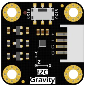
The DFRobot SEN0409 is a 3-axis accelerometer designed to measure acceleration in three dimensions: X, Y, and Z. This sensor is ideal for applications requiring motion detection, orientation tracking, and tilt sensing. Its compact design and high sensitivity make it suitable for use in robotics, mobile devices, gaming controllers, and wearable technology.
The SEN0409 provides accurate acceleration data, enabling users to detect movement, measure vibration, and determine the orientation of objects. It is compatible with microcontrollers such as Arduino, making it a versatile choice for hobbyists and professionals alike.
Explore Projects Built with 3-axis accelerometer dfrobot sen0409
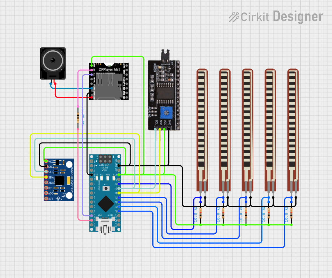
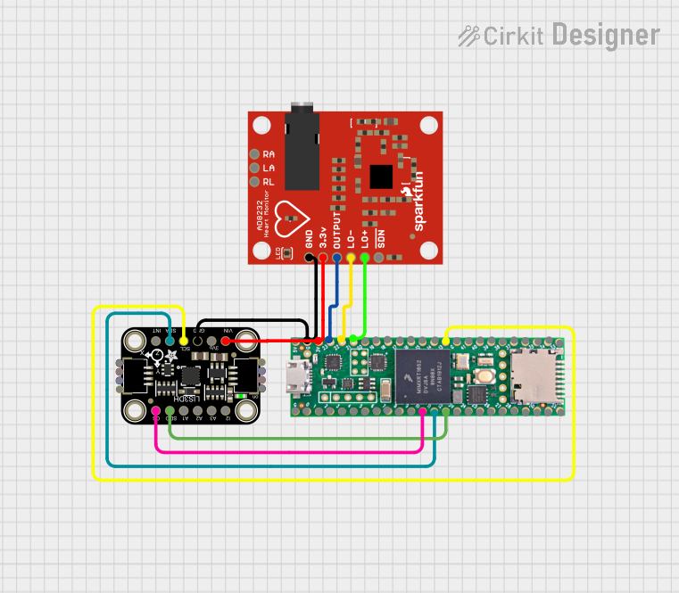
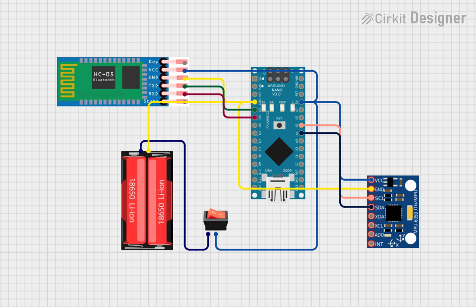
Explore Projects Built with 3-axis accelerometer dfrobot sen0409
Technical Specifications
- Manufacturer: DFRobot
- Model: SEN0409
- Measurement Range: ±2g, ±4g, ±8g, ±16g (configurable)
- Supply Voltage: 3.3V to 5V
- Communication Interface: I2C
- I2C Address: 0x18 (default)
- Operating Temperature: -40°C to +85°C
- Dimensions: 20mm x 20mm
Pin Configuration and Descriptions
The SEN0409 has a 6-pin interface for easy integration into circuits. The table below describes each pin:
| Pin | Name | Description |
|---|---|---|
| 1 | VCC | Power supply input (3.3V to 5V) |
| 2 | GND | Ground connection |
| 3 | SDA | I2C data line |
| 4 | SCL | I2C clock line |
| 5 | INT1 | Interrupt 1 output (optional) |
| 6 | INT2 | Interrupt 2 output (optional) |
Usage Instructions
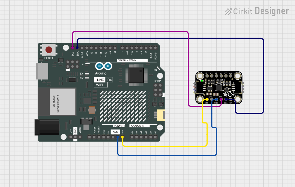
Connecting the SEN0409 to an Arduino UNO
To use the SEN0409 with an Arduino UNO, follow these steps:
- Connect the VCC pin of the SEN0409 to the 5V pin on the Arduino.
- Connect the GND pin of the SEN0409 to the GND pin on the Arduino.
- Connect the SDA pin of the SEN0409 to the A4 pin on the Arduino (I2C data line).
- Connect the SCL pin of the SEN0409 to the A5 pin on the Arduino (I2C clock line).
Sample Arduino Code
The following code demonstrates how to read acceleration data from the SEN0409 using the Arduino IDE:
#include <Wire.h>

// I2C address of the SEN0409 accelerometer
#define ACCELEROMETER_ADDR 0x18

// Register addresses for acceleration data
#define OUT_X_L 0x28
#define OUT_X_H 0x29
#define OUT_Y_L 0x2A
#define OUT_Y_H 0x2B
#define OUT_Z_L 0x2C
#define OUT_Z_H 0x2D

void setup() {
  Wire.begin(); // Initialize I2C communication
  Serial.begin(9600); // Start serial communication for debugging

  // Initialize the accelerometer
  Wire.beginTransmission(ACCELEROMETER_ADDR);
  Wire.write(0x20); // CTRL_REG1: Enable the accelerometer
  Wire.write(0x57); // Set data rate to 100Hz, enable all axes
  Wire.endTransmission();
}

void loop() {
  int16_t x, y, z;

  // Read X-axis acceleration
  x = readAxis(OUT_X_L, OUT_X_H);

  // Read Y-axis acceleration
  y = readAxis(OUT_Y_L, OUT_Y_H);

  // Read Z-axis acceleration
  z = readAxis(OUT_Z_L, OUT_Z_H);

  // Print acceleration values to the Serial Monitor
  Serial.print("X: ");
  Serial.print(x);
  Serial.print(" Y: ");
  Serial.print(y);
  Serial.print(" Z: ");
  Serial.println(z);

  delay(500); // Wait for 500ms before the next reading
}

// Function to read acceleration data for a specific axis
int16_t readAxis(uint8_t lowReg, uint8_t highReg) {
  Wire.beginTransmission(ACCELEROMETER_ADDR);
  Wire.write(lowReg); // Request low byte
  Wire.endTransmission(false);
  Wire.requestFrom(ACCELEROMETER_ADDR, 1);
  uint8_t lowByte = Wire.read();

  Wire.beginTransmission(ACCELEROMETER_ADDR);
  Wire.write(highReg); // Request high byte
  Wire.endTransmission(false);
  Wire.requestFrom(ACCELEROMETER_ADDR, 1);
  uint8_t highByte = Wire.read();

  // Combine high and low bytes into a 16-bit value
  return (int16_t)((highByte << 8) | lowByte);
}
Important Considerations
- Ensure the I2C address (default: 0x18) matches the address configured in your code.
- Use pull-up resistors (typically 4.7kΩ) on the SDA and SCL lines if they are not already present on your board.
- Avoid exposing the sensor to extreme temperatures or mechanical shocks to maintain accuracy.
Troubleshooting and FAQs
Common Issues
No data is being read from the sensor.
- Ensure the wiring is correct and matches the pin configuration.
- Verify that the I2C address in the code matches the sensor's default address (0x18).
The sensor outputs incorrect or unstable values.
- Check the power supply voltage (3.3V to 5V) and ensure it is stable.
- Verify that the sensor is securely mounted and not subject to excessive vibration.
The Arduino cannot detect the sensor on the I2C bus.
- Use an I2C scanner sketch to confirm the sensor's address.
- Ensure pull-up resistors are present on the SDA and SCL lines.
Tips for Troubleshooting
- Use a multimeter to check the connections and ensure proper voltage levels.
- Test the sensor with a different microcontroller or I2C device to rule out hardware issues.
- Consult the DFRobot SEN0409 datasheet for additional technical details and configuration options.