How to Use R4 minima: Examples, Pinouts, and Specs
Introduction
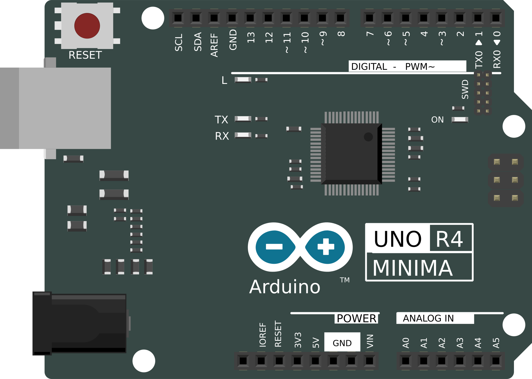
The R4 Minima is a resistor commonly used in electronic circuits to represent a minimum resistance value. It ensures that the current flow in a circuit is maintained at a specified level, preventing excessive current that could damage components. This resistor is a fundamental component in circuit design, often used for current limiting, voltage division, and signal conditioning.
Explore Projects Built with R4 minima
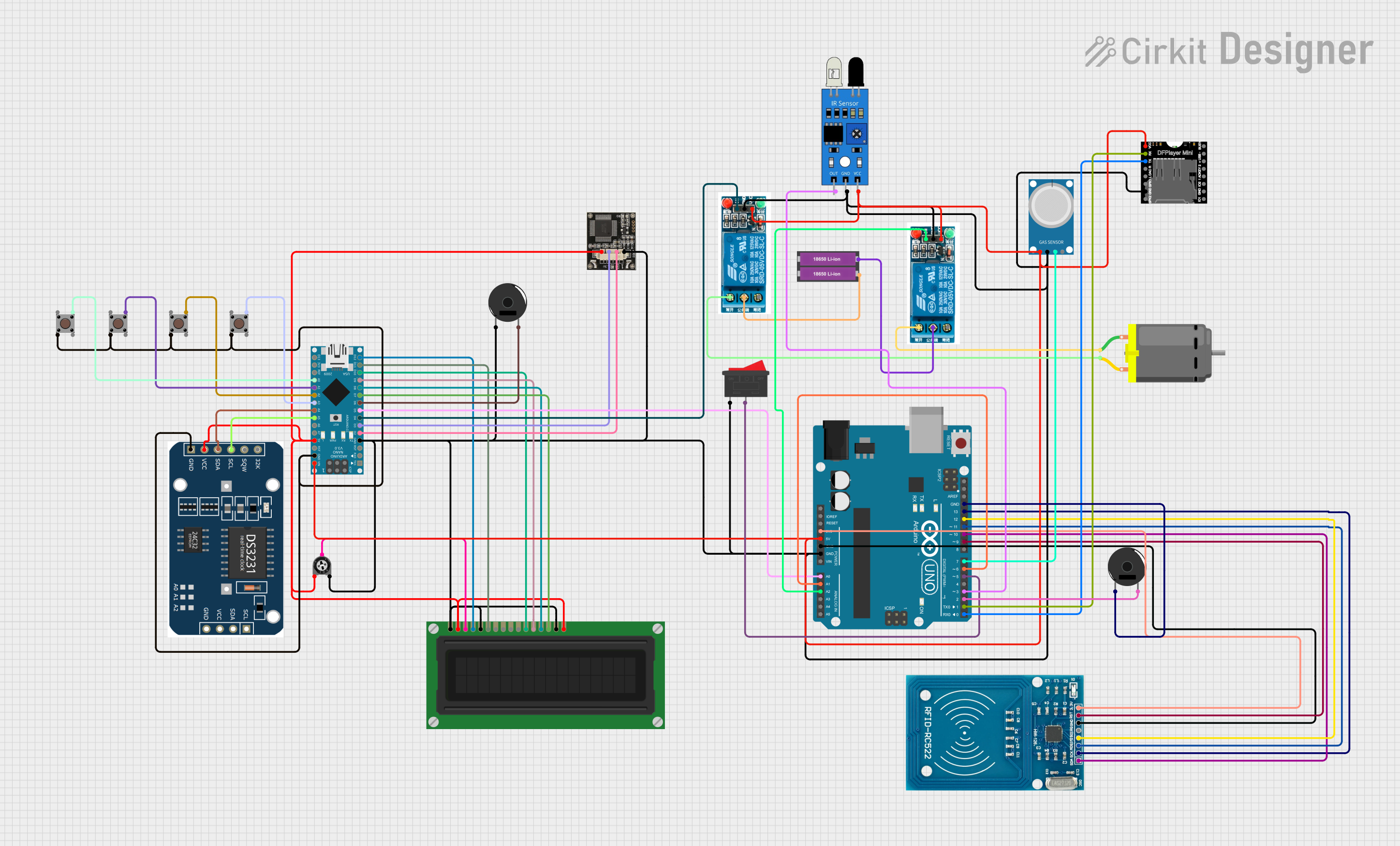
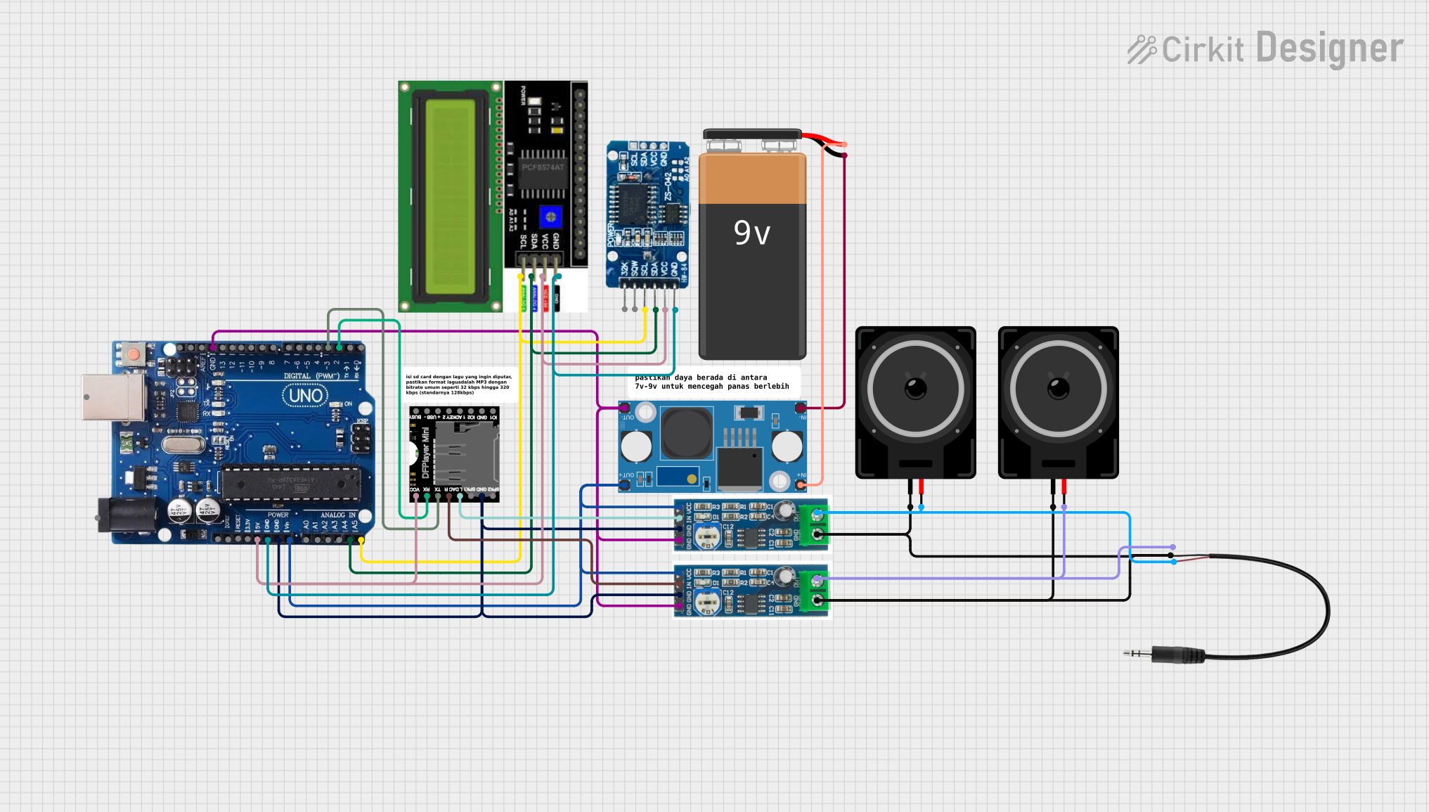
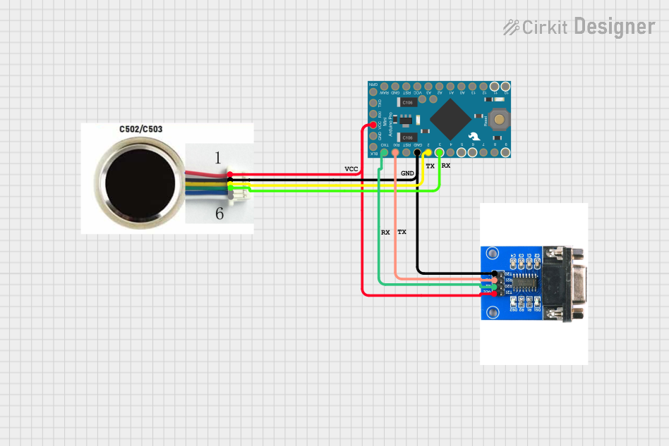

Explore Projects Built with R4 minima
Common Applications and Use Cases
- Current Limiting: Protects sensitive components like LEDs or ICs by restricting current flow.
- Voltage Division: Used in voltage divider circuits to create reference voltages.
- Pull-Up or Pull-Down Resistors: Ensures stable logic levels in digital circuits.
- Signal Conditioning: Helps in filtering or impedance matching in analog circuits.
Technical Specifications
Below are the key technical details of the R4 Minima resistor:
| Parameter | Value |
|---|---|
| Resistance Value | 1 Ω (minimum resistance) |
| Tolerance | ±5% (standard) |
| Power Rating | 0.25 W (1/4 Watt) |
| Maximum Voltage Rating | 250 V |
| Temperature Coefficient | ±200 ppm/°C |
| Operating Temperature | -55°C to +155°C |
Pin Configuration and Descriptions
The R4 Minima is a two-terminal passive component. Below is the pin configuration:
| Pin | Description |
|---|---|
| Pin 1 | Connects to the input voltage or signal |
| Pin 2 | Connects to the output or ground |
Usage Instructions
How to Use the R4 Minima in a Circuit
- Determine the Required Resistance: Ensure that the R4 Minima's 1 Ω resistance value is suitable for your application.
- Connect the Resistor:
- For current limiting, place the resistor in series with the load.
- For voltage division, use the R4 Minima in combination with another resistor.
- Verify Power Dissipation: Ensure the resistor's power rating (0.25 W) is not exceeded. Use the formula: [ P = I^2 \times R ] where ( P ) is power, ( I ) is current, and ( R ) is resistance.
- Soldering: If soldering the resistor onto a PCB, ensure proper heat management to avoid damaging the component.
Important Considerations and Best Practices
- Avoid Overloading: Do not exceed the resistor's power or voltage rating to prevent overheating or failure.
- Check Tolerance: The ±5% tolerance means the actual resistance may vary slightly from the nominal value.
- Temperature Effects: Be mindful of the temperature coefficient, as resistance may change with temperature variations.
- Use in High-Frequency Circuits: For high-frequency applications, consider the resistor's parasitic inductance and capacitance.
Example: Using R4 Minima with an Arduino UNO
The R4 Minima can be used as a current-limiting resistor for an LED connected to an Arduino UNO. Below is an example circuit and code:
Circuit Setup
- Connect one terminal of the R4 Minima to an Arduino digital pin (e.g., Pin 13).
- Connect the other terminal of the resistor to the anode (+) of the LED.
- Connect the cathode (-) of the LED to the Arduino's GND.
Arduino Code
// Simple LED Blink Example with R4 Minima Resistor
// The R4 Minima (1 Ω) is used to limit current to the LED.

const int ledPin = 13; // Pin connected to the LED

void setup() {
  pinMode(ledPin, OUTPUT); // Set the LED pin as an output
}

void loop() {
  digitalWrite(ledPin, HIGH); // Turn the LED on
  delay(1000);                // Wait for 1 second
  digitalWrite(ledPin, LOW);  // Turn the LED off
  delay(1000);                // Wait for 1 second
}
Troubleshooting and FAQs
Common Issues and Solutions
Resistor Overheating
- Cause: Exceeding the power rating of 0.25 W.
- Solution: Reduce the current or use a resistor with a higher power rating.
Incorrect Resistance Value
- Cause: Manufacturing tolerance or incorrect resistor selection.
- Solution: Measure the resistor with a multimeter to verify its value.
Circuit Not Functioning as Expected
- Cause: Incorrect placement of the resistor in the circuit.
- Solution: Double-check the circuit connections and ensure the resistor is placed correctly.
LED Not Lighting Up in Arduino Circuit
- Cause: Insufficient current due to the resistor value.
- Solution: Verify the resistor value and ensure it is appropriate for the LED's forward voltage and current requirements.
FAQs
Q: Can I use the R4 Minima in high-power applications?
A: No, the R4 Minima has a power rating of 0.25 W. For high-power applications, use a resistor with a higher power rating.
Q: How do I identify the R4 Minima resistor?
A: The R4 Minima typically has color bands indicating its resistance value (1 Ω) and tolerance (±5%). Refer to a resistor color code chart for details.
Q: Can I use the R4 Minima in AC circuits?
A: Yes, the R4 Minima can be used in both AC and DC circuits, provided its voltage and power ratings are not exceeded.
Q: What happens if I use a resistor with a lower resistance value?
A: Using a lower resistance value may result in higher current flow, potentially damaging other components in the circuit.
This concludes the documentation for the R4 Minima resistor.