Cirkit Designer Logo
Cirkit Designer
Your all-in-one circuit design IDE
Home / 
Component Documentation

How to Use VL53L1X: Examples, Pinouts, and Specs

Image of VL53L1X
Cirkit Designer LogoDesign with VL53L1X in Cirkit Designer

Introduction

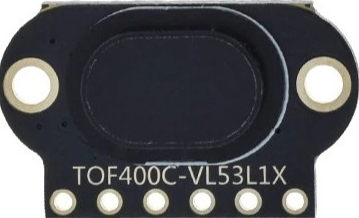
The VL53L1X is a state-of-the-art, Time-of-Flight (ToF) laser-ranging sensor, enhancing the STMicroelectronics FlightSense™ product family. It is a fast and accurate sensor that measures the distance to a target by timing the flight of a very short pulse of laser light. This component is widely used in robotics, user detection, drones, IoT devices, and many other applications where accurate distance measurement is required.

Explore Projects Built with VL53L1X

Use Cirkit Designer to design, explore, and prototype these projects online. Some projects support real-time simulation. Click "Open Project" to start designing instantly!
Arduino UNO with A9G GSM/GPRS and Dual VL53L1X Distance Sensors
Image of TED CIRCUIT : A project utilizing VL53L1X in a practical application
This circuit features an Arduino UNO microcontroller interfaced with an A9G GSM/GPRS+GPS/BDS module and two VL53L1X time-of-flight distance sensors. The A9G module is connected to the Arduino via serial communication for GPS and GSM functionalities, while both VL53L1X sensors are connected through I2C with shared SDA and SCL lines and individual SHUT pins for selective sensor activation. The Arduino is programmed to control these peripherals, although the specific functionality is not detailed in the provided code.
Cirkit Designer LogoOpen Project in Cirkit Designer
Arduino 101 Controlled Robotic Arm with VL53L1X Distance Sensor
Image of Mg996R Vl503lox robotic arm: A project utilizing VL53L1X in a practical application
This circuit features an Arduino 101 microcontroller interfaced with a VL53L1X distance sensor and five MG996R servo motors. The Arduino 101 controls the servos via PWM signals and reads distance measurements from the sensor over I2C, with power supplied through a power jack.
Cirkit Designer LogoOpen Project in Cirkit Designer
Arduino 101 Controlled Distance Measurement and Display with VL53L1X and I2C LCD
Image of TOF project: A project utilizing VL53L1X in a practical application
This circuit features an Arduino 101 microcontroller interfaced with a VL53L1X time-of-flight distance sensor and an I2C LCD 16x2 display. The Arduino provides power to both the sensor and the display and communicates with them via the I2C bus (SDA/SCL lines). Additionally, there is a red LED with a series resistor connected to one of the Arduino's digital pins, likely for indication purposes.
Cirkit Designer LogoOpen Project in Cirkit Designer
Arduino Mega 2560-Based Multi-Sensor System with Distance, Magnetometer, and Camera Integration
Image of Junior Design - Sensors: A project utilizing VL53L1X in a practical application
This circuit features an Arduino Mega 2560 microcontroller interfaced with multiple VL53L0X distance sensors, an OV7725 camera module, and an Adafruit LIS3MDL triple-axis magnetometer. The Arduino reads data from these sensors and the camera, likely for a robotics or environmental sensing application, and processes the data for further use or transmission.
Cirkit Designer LogoOpen Project in Cirkit Designer

Explore Projects Built with VL53L1X

Use Cirkit Designer to design, explore, and prototype these projects online. Some projects support real-time simulation. Click "Open Project" to start designing instantly!
Image of TED CIRCUIT : A project utilizing VL53L1X in a practical application
Arduino UNO with A9G GSM/GPRS and Dual VL53L1X Distance Sensors
This circuit features an Arduino UNO microcontroller interfaced with an A9G GSM/GPRS+GPS/BDS module and two VL53L1X time-of-flight distance sensors. The A9G module is connected to the Arduino via serial communication for GPS and GSM functionalities, while both VL53L1X sensors are connected through I2C with shared SDA and SCL lines and individual SHUT pins for selective sensor activation. The Arduino is programmed to control these peripherals, although the specific functionality is not detailed in the provided code.
Cirkit Designer LogoOpen Project in Cirkit Designer
Image of Mg996R Vl503lox robotic arm: A project utilizing VL53L1X in a practical application
Arduino 101 Controlled Robotic Arm with VL53L1X Distance Sensor
This circuit features an Arduino 101 microcontroller interfaced with a VL53L1X distance sensor and five MG996R servo motors. The Arduino 101 controls the servos via PWM signals and reads distance measurements from the sensor over I2C, with power supplied through a power jack.
Cirkit Designer LogoOpen Project in Cirkit Designer
Image of TOF project: A project utilizing VL53L1X in a practical application
Arduino 101 Controlled Distance Measurement and Display with VL53L1X and I2C LCD
This circuit features an Arduino 101 microcontroller interfaced with a VL53L1X time-of-flight distance sensor and an I2C LCD 16x2 display. The Arduino provides power to both the sensor and the display and communicates with them via the I2C bus (SDA/SCL lines). Additionally, there is a red LED with a series resistor connected to one of the Arduino's digital pins, likely for indication purposes.
Cirkit Designer LogoOpen Project in Cirkit Designer
Image of Junior Design - Sensors: A project utilizing VL53L1X in a practical application
Arduino Mega 2560-Based Multi-Sensor System with Distance, Magnetometer, and Camera Integration
This circuit features an Arduino Mega 2560 microcontroller interfaced with multiple VL53L0X distance sensors, an OV7725 camera module, and an Adafruit LIS3MDL triple-axis magnetometer. The Arduino reads data from these sensors and the camera, likely for a robotics or environmental sensing application, and processes the data for further use or transmission.
Cirkit Designer LogoOpen Project in Cirkit Designer

Common Applications and Use Cases

  • Autonomous navigation (robots, drones)
  • User detection for power-saving
  • Object detection and avoidance
  • Gesture recognition
  • Indoor mapping

Technical Specifications

Key Technical Details

  • Type: ToF (Time-of-Flight) ranging sensor
  • Operating Voltage: 2.6V to 3.5V
  • Peak Current: 20 mA
  • Maximum Ranging Distance: Up to 4 meters
  • Ranging Accuracy: ±25 mm
  • Interface: I2C
  • Field of View: 27°

Pin Configuration and Descriptions

Pin Number Name Description
1 VDD Power supply (2.6V to 3.5V)
2 GND Ground connection
3 SCL I2C clock line
4 SDA I2C data line
5 GPIO1 Programmable interrupt output
6 XSHUT Active-low shutdown input

Usage Instructions

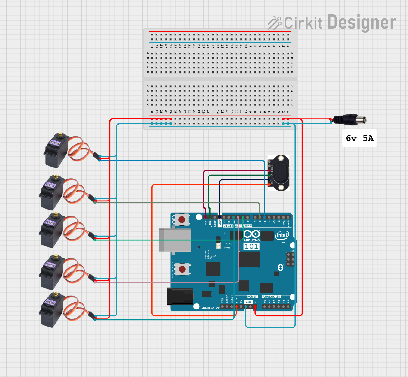
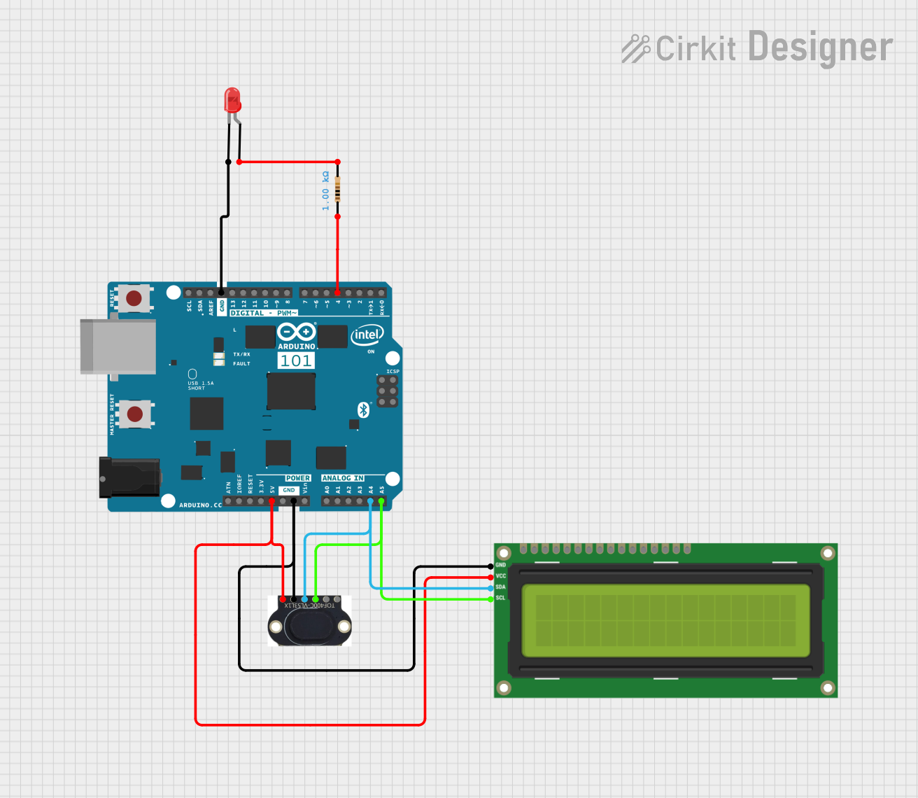
How to Use the Component in a Circuit

  1. Power Supply: Connect the VDD pin to a 2.6V to 3.5V power source and the GND pin to the ground.
  2. I2C Communication: Connect the SCL and SDA pins to the I2C clock and data lines, respectively.
  3. Interrupts (Optional): The GPIO1 can be used for interrupt-driven measurements.
  4. Shutdown Control (Optional): The XSHUT pin can be driven low to put the sensor into a hardware shutdown state.

Important Considerations and Best Practices

  • Ensure that the power supply is stable and within the specified voltage range.
  • Use pull-up resistors on the I2C lines as required by your microcontroller's I2C interface.
  • Avoid exposing the sensor to direct sunlight or strong infrared sources to prevent measurement errors.
  • For accurate measurements, ensure that the path between the sensor and the target is unobstructed.

Example Code for Arduino UNO

#include <Wire.h>
#include <VL53L1X.h>

VL53L1X sensor;

void setup() {
  Serial.begin(9600);
  Wire.begin();

  sensor.setTimeout(500);
  if (!sensor.init()) {
    Serial.println("Failed to detect and initialize sensor!");
    while (1);
  }

  sensor.startContinuous(50);
}

void loop() {
  Serial.print("Distance: ");
  Serial.print(sensor.read());
  if (sensor.timeoutOccurred()) { Serial.print(" TIMEOUT"); }

  Serial.println();
}

Troubleshooting and FAQs

Common Issues

  • No Data from Sensor: Ensure that the I2C connections are correct and that the sensor is properly powered.
  • Inaccurate Readings: Check for obstructions or reflective surfaces near the sensor that may cause incorrect readings.
  • Sensor Not Detected: Verify that the XSHUT pin is not being held low, preventing the sensor from starting up.

Solutions and Tips for Troubleshooting

  • Double-check wiring, especially the I2C lines and pull-up resistors.
  • Use the sensor.setTimeout() function to handle cases where the sensor does not respond.
  • Ensure that the sensor is not facing any bright light sources directly.

FAQs

Q: What is the maximum range of the VL53L1X sensor? A: The VL53L1X can measure distances up to 4 meters.

Q: Can the VL53L1X sensor measure distances through glass or transparent objects? A: The sensor may not work reliably through transparent materials as the light pulse may not reflect back correctly.

Q: Is the VL53L1X sensor waterproof? A: No, the VL53L1X is not waterproof and should be protected from moisture and water exposure.

Q: How can I reduce the power consumption of the sensor? A: You can reduce the measurement frequency or use the XSHUT pin to put the sensor into a low-power state when not in use.

Q: Can I use multiple VL53L1X sensors on the same I2C bus? A: Yes, you can use multiple sensors on the same I2C bus by changing their I2C addresses or using the XSHUT pin to selectively activate them.