How to Use Relay 3 Channel Optocoupler: Examples, Pinouts, and Specs
Introduction
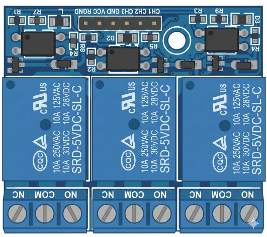
The Relay 3 Channel Optocoupler module, manufactured by Arduino (Part ID: Relay), is a versatile electronic component designed to control high-voltage devices using low-voltage signals. It features three independent relays, each capable of switching AC or DC loads, and optocoupler isolation to protect the controlling circuit from high-voltage spikes or interference. This module is ideal for applications requiring safe and reliable control of appliances, motors, or other high-power devices.
Explore Projects Built with Relay 3 Channel Optocoupler


Explore Projects Built with Relay 3 Channel Optocoupler
Common Applications and Use Cases
- Home automation systems (e.g., controlling lights, fans, or appliances)
- Industrial automation and motor control
- IoT projects requiring high-voltage device control
- Robotics and mechatronics systems
- Signal isolation in sensitive circuits
Technical Specifications
Key Technical Details
- Operating Voltage: 5V DC
- Relay Channels: 3
- Relay Type: SPDT (Single Pole Double Throw)
- Maximum Load (per channel):
- AC: 250V at 10A
- DC: 30V at 10A
- Trigger Voltage: 3.3V to 5V (compatible with Arduino and other microcontrollers)
- Optocoupler Isolation: Yes
- LED Indicators: One per channel (indicates relay activation)
- Dimensions: 50mm x 40mm x 20mm (approx.)
Pin Configuration and Descriptions
The module has two main interfaces: the control pins and the relay output terminals.
Control Pins
| Pin Name | Description |
|---|---|
| VCC | 5V power supply input |
| GND | Ground connection |
| IN1 | Control signal for Relay 1 (active LOW) |
| IN2 | Control signal for Relay 2 (active LOW) |
| IN3 | Control signal for Relay 3 (active LOW) |
Relay Output Terminals (per channel)
| Terminal | Description |
|---|---|
| COM | Common terminal for the relay |
| NO | Normally Open terminal (connected to COM when active) |
| NC | Normally Closed terminal (connected to COM when idle) |
Usage Instructions
How to Use the Component in a Circuit
- Power the Module: Connect the VCC pin to a 5V power source and the GND pin to ground.
- Connect Control Signals: Use digital output pins from a microcontroller (e.g., Arduino UNO) to control the IN1, IN2, and IN3 pins. A LOW signal activates the corresponding relay.
- Connect the Load: Wire the high-voltage device to the relay output terminals (COM, NO, and NC) as per your application:
- Use the NO terminal for devices that should be off by default and turn on when the relay is activated.
- Use the NC terminal for devices that should be on by default and turn off when the relay is activated.
- Test the Circuit: Upload the control code to your microcontroller and verify the relay operation.
Important Considerations and Best Practices
- Ensure the load current and voltage do not exceed the relay's maximum ratings.
- Use proper insulation and safety precautions when working with high-voltage circuits.
- Avoid switching inductive loads (e.g., motors) without a flyback diode or snubber circuit to prevent voltage spikes.
- Keep the module away from moisture and conductive surfaces to prevent short circuits.
Example Code for Arduino UNO
// Example code to control a 3 Channel Relay module with Arduino UNO
// This code toggles each relay ON and OFF with a 1-second delay

// Define the control pins for the relays
#define RELAY1 2  // Relay 1 control pin connected to Arduino pin 2
#define RELAY2 3  // Relay 2 control pin connected to Arduino pin 3
#define RELAY3 4  // Relay 3 control pin connected to Arduino pin 4

void setup() {
  // Set relay control pins as outputs
  pinMode(RELAY1, OUTPUT);
  pinMode(RELAY2, OUTPUT);
  pinMode(RELAY3, OUTPUT);

  // Initialize all relays to OFF state (HIGH signal)
  digitalWrite(RELAY1, HIGH);
  digitalWrite(RELAY2, HIGH);
  digitalWrite(RELAY3, HIGH);
}

void loop() {
  // Turn Relay 1 ON
  digitalWrite(RELAY1, LOW); // Active LOW signal turns the relay ON
  delay(1000);               // Wait for 1 second

  // Turn Relay 1 OFF and Relay 2 ON
  digitalWrite(RELAY1, HIGH); // Turn Relay 1 OFF
  digitalWrite(RELAY2, LOW);  // Turn Relay 2 ON
  delay(1000);                // Wait for 1 second

  // Turn Relay 2 OFF and Relay 3 ON
  digitalWrite(RELAY2, HIGH); // Turn Relay 2 OFF
  digitalWrite(RELAY3, LOW);  // Turn Relay 3 ON
  delay(1000);                // Wait for 1 second

  // Turn all relays OFF
  digitalWrite(RELAY3, HIGH); // Turn Relay 3 OFF
  delay(1000);                // Wait for 1 second
}
Troubleshooting and FAQs
Common Issues and Solutions
Relays Not Activating:
- Ensure the module is powered with a stable 5V supply.
- Verify that the control signals (IN1, IN2, IN3) are correctly connected and set to LOW to activate the relays.
- Check for loose or incorrect wiring.
High-Voltage Device Not Responding:
- Confirm that the device is properly connected to the relay output terminals (COM, NO, or NC).
- Ensure the device's voltage and current requirements are within the relay's specifications.
Interference or Unstable Operation:
- Use a separate power supply for the relay module if the microcontroller's power source is insufficient.
- Add a flyback diode across inductive loads to suppress voltage spikes.
FAQs
Q1: Can I use this module with a 3.3V microcontroller?
A1: Yes, the module is compatible with 3.3V control signals, but ensure the VCC pin is still powered with 5V.
Q2: How do I know if a relay is active?
A2: Each relay has an LED indicator that lights up when the relay is activated.
Q3: Can I control AC and DC loads simultaneously?
A3: Yes, each relay channel is independent, so you can control a mix of AC and DC loads as long as they meet the relay's specifications.