How to Use M26X-12 Relays Expansion Board: Examples, Pinouts, and Specs
Introduction
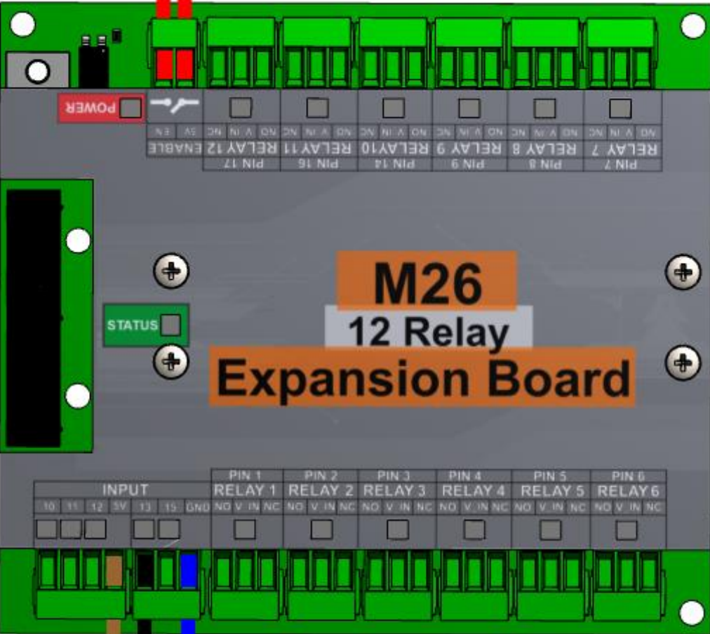
The M26X-12 Relays Expansion Board (Manufacturer Part ID: M26 – 12 Rev. 6.2) is a versatile relay module designed by CNC4PC. It allows users to control up to 12 devices using low-power control signals. This board is ideal for applications requiring the automation of electrical devices, such as home automation, industrial control systems, and robotics.
The board is equipped with 12 relay outputs, each capable of switching high-power loads, making it suitable for controlling lights, motors, solenoids, and other electrical devices. Its compact design and ease of integration make it a popular choice for both hobbyists and professionals.
Explore Projects Built with M26X-12 Relays Expansion Board


Explore Projects Built with M26X-12 Relays Expansion Board
Common Applications
- Home Automation: Controlling lights, fans, and other household appliances.
- Industrial Automation: Managing motors, pumps, and other machinery.
- Robotics: Actuating solenoids, motors, or other robotic components.
- IoT Projects: Enabling remote control of devices via microcontrollers or IoT platforms.
Technical Specifications
Key Technical Details
| Parameter | Specification |
|---|---|
| Manufacturer | CNC4PC |
| Model Number | M26 – 12 Rev. 6.2 |
| Number of Relays | 12 |
| Relay Type | SPDT (Single Pole Double Throw) |
| Control Voltage | 5V DC |
| Operating Voltage Range | 12V DC |
| Maximum Load (per relay) | 10A @ 250V AC or 10A @ 30V DC |
| Dimensions | 150mm x 100mm x 20mm |
| Mounting Type | PCB Mount with screw terminals |
| Isolation | Optocoupler isolation for each relay |
Pin Configuration and Descriptions
The M26X-12 Relays Expansion Board features a set of input pins for control signals and output terminals for connecting devices. Below is the pin configuration:
Input Pins (Control Signals)
| Pin Label | Description |
|---|---|
| IN1–IN12 | Control inputs for relays 1 to 12 |
| GND | Ground connection |
| VCC | 5V DC power supply for control logic |
Output Terminals (Relay Outputs)
| Terminal Label | Description |
|---|---|
| COM1–COM12 | Common terminal for relays 1 to 12 |
| NO1–NO12 | Normally Open terminal for relays |
| NC1–NC12 | Normally Closed terminal for relays |
Usage Instructions
How to Use the Component in a Circuit
- Power the Board: Connect a 12V DC power supply to the board's power input terminals.
- Connect Control Signals: Use a microcontroller (e.g., Arduino UNO) or other control device to send 5V signals to the IN1–IN12 pins. Each pin corresponds to a specific relay.
- Connect Devices: Attach the devices you want to control to the relay output terminals (COM, NO, NC). For example:
- Use the COM and NO terminals for devices that should be off by default and turn on when the relay is activated.
- Use the COM and NC terminals for devices that should be on by default and turn off when the relay is activated.
- Test the Setup: Activate the control signals to test the relays and ensure proper operation.
Important Considerations and Best Practices
- Isolation: The board uses optocouplers to isolate the control signals from the high-power relay circuits. Ensure proper grounding to avoid electrical noise or interference.
- Power Supply: Use a stable 12V DC power supply to power the relays. Avoid exceeding the maximum load ratings of the relays.
- Heat Dissipation: If multiple relays are switching high-power loads simultaneously, ensure adequate ventilation to prevent overheating.
- Safety: When working with high voltages, take necessary precautions to avoid electric shock or damage to connected devices.
Example: Connecting to an Arduino UNO
Below is an example of how to control the M26X-12 Relays Expansion Board using an Arduino UNO:
Circuit Connections
- Connect the VCC and GND pins of the relay board to the 5V and GND pins of the Arduino.
- Connect the IN1 pin of the relay board to Arduino digital pin 2.
- Connect a 12V DC power supply to the relay board's power input terminals.
- Connect a device (e.g., a light bulb) to the COM1 and NO1 terminals of the relay.
Arduino Code
// Example code to control a single relay on the M26X-12 Relays Expansion Board
// This code toggles the relay connected to IN1 on and off every second.

#define RELAY_PIN 2  // Arduino pin connected to IN1 on the relay board

void setup() {
  pinMode(RELAY_PIN, OUTPUT);  // Set the relay pin as an output
  digitalWrite(RELAY_PIN, LOW);  // Ensure the relay is off initially
}

void loop() {
  digitalWrite(RELAY_PIN, HIGH);  // Turn the relay on
  delay(1000);  // Wait for 1 second
  digitalWrite(RELAY_PIN, LOW);  // Turn the relay off
  delay(1000);  // Wait for 1 second
}
Troubleshooting and FAQs
Common Issues and Solutions
Relays Not Activating
- Cause: Insufficient control voltage or incorrect wiring.
- Solution: Ensure the control voltage is 5V DC and verify the connections to the IN pins.
Devices Not Responding
- Cause: Incorrect wiring of the relay output terminals.
- Solution: Double-check the connections to the COM, NO, and NC terminals.
Overheating
- Cause: Relays switching high-power loads continuously.
- Solution: Reduce the load on the relays or improve ventilation around the board.
Electrical Noise or Interference
- Cause: Poor grounding or lack of isolation.
- Solution: Ensure proper grounding and use shielded cables if necessary.
FAQs
Q: Can I use a 3.3V microcontroller with this board?
- A: No, the control voltage must be 5V DC. Use a level shifter if your microcontroller operates at 3.3V.
Q: What happens if I exceed the maximum load rating of a relay?
- A: Exceeding the load rating can damage the relay and potentially cause a fire hazard. Always stay within the specified limits.
Q: Can I control all 12 relays simultaneously?
- A: Yes, but ensure your power supply can handle the combined current draw of all active relays.
Q: Is the board compatible with Raspberry Pi?
- A: Yes, but you may need a level shifter to convert the Raspberry Pi's 3.3V GPIO signals to 5V.
This documentation provides a comprehensive guide to using the M26X-12 Relays Expansion Board. For further assistance, refer to the manufacturer's datasheet or contact CNC4PC support.