
How to Use 25mm Dial Potentiometer with switch: Examples, Pinouts, and Specs

 Design with 25mm Dial Potentiometer with switch in Cirkit Designer
Introduction
The 25mm Dial Potentiometer with Switch is a versatile electronic component that combines a variable resistor and an integrated on/off switch. It features a rotary knob for manual adjustment of resistance, allowing users to control voltage or current in a circuit. The built-in switch adds functionality for toggling power, making it ideal for applications where both adjustment and power control are required.
Explore Projects Built with 25mm Dial Potentiometer with switch
 Open Project in Cirkit Designer
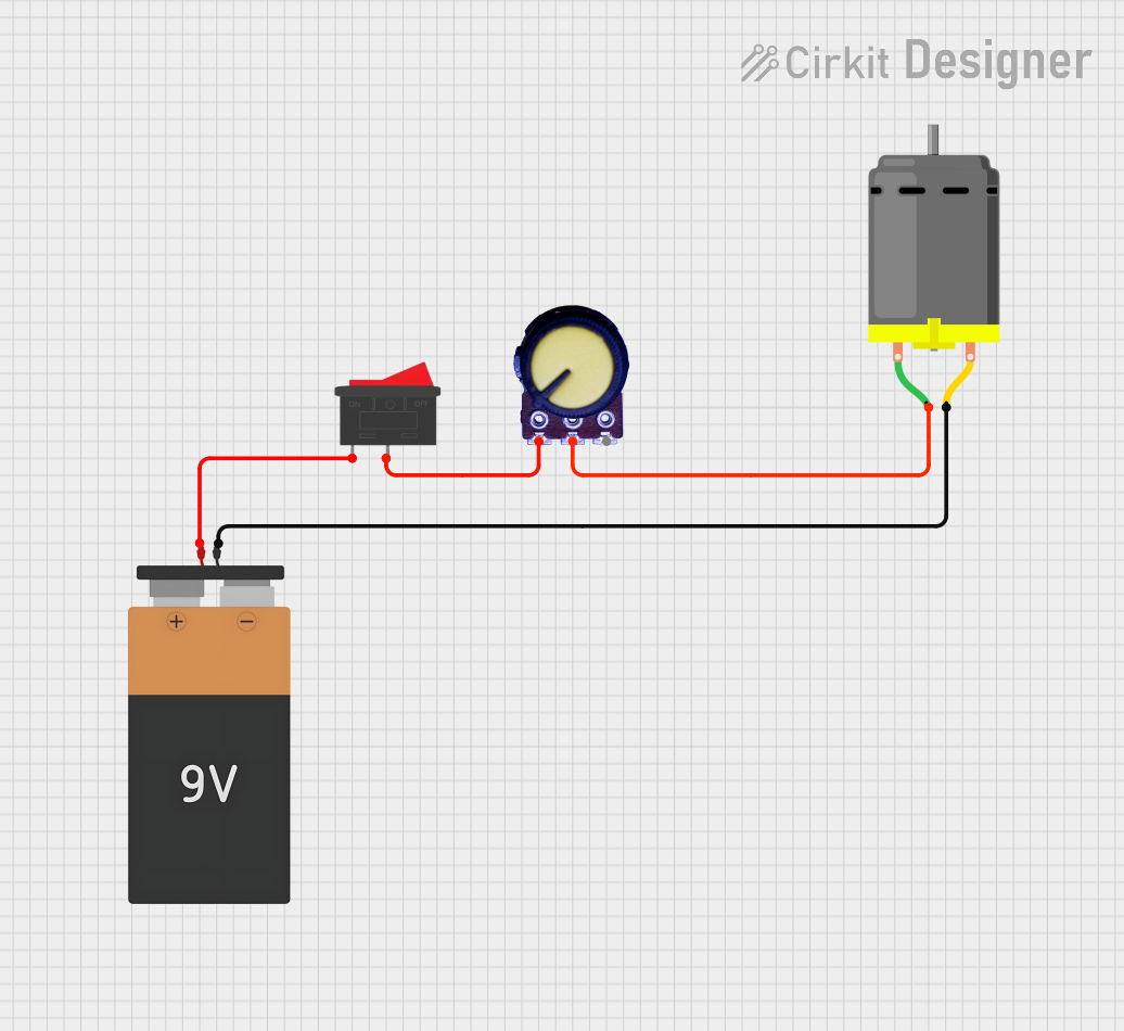 Open Project in Cirkit Designer
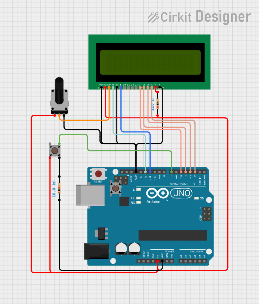 Open Project in Cirkit Designer
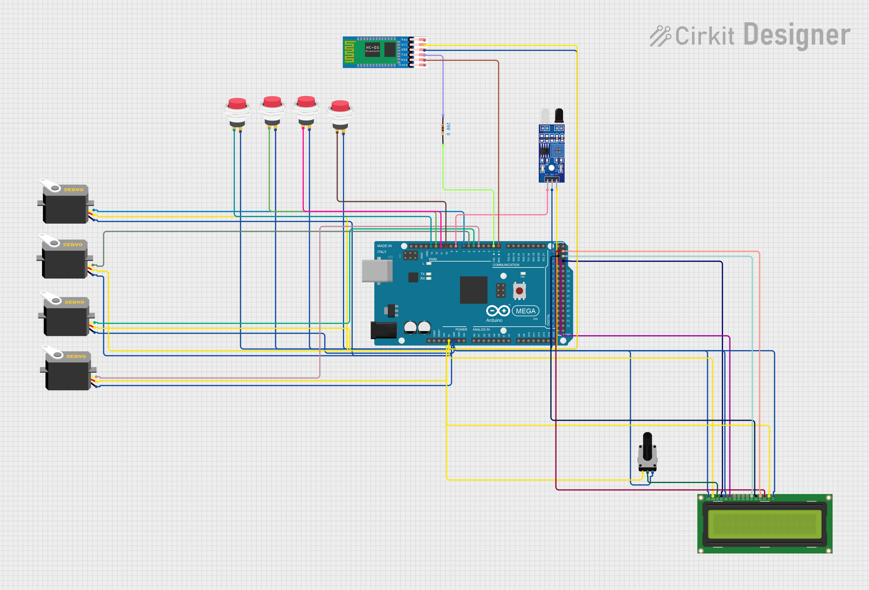 Open Project in Cirkit Designer
Explore Projects Built with 25mm Dial Potentiometer with switch
Open Project in Cirkit DesignerOpen Project in Cirkit DesignerOpen Project in Cirkit DesignerOpen Project in Cirkit DesignerCommon Applications and Use Cases
- Volume control in audio devices
- Brightness adjustment in LED circuits
- Speed control in DC motor applications
- Power control in small appliances
- User interfaces for electronic projects
Technical Specifications
Below are the key technical details and pin configuration for the 25mm Dial Potentiometer with Switch:
Key Technical Details
| Parameter | Specification |
|---|---|
| Resistance Range | 10 kΩ (typical) |
| Tolerance | ±20% |
| Power Rating | 0.5 W |
| Operating Voltage | 0–50 V DC |
| Switch Type | SPST (Single Pole Single Throw) |
| Switch Rating | 1 A at 30 V DC |
| Rotation Angle | 300° (approx.) |
| Shaft Diameter | 6 mm |
| Body Diameter | 25 mm |
| Operating Temperature | -10°C to +70°C |
Pin Configuration and Descriptions
| Pin Number | Pin Name | Description |
|---|---|---|
| 1 | Terminal 1 | One end of the resistive track |
| 2 | Wiper | Adjustable middle point of the resistive track |
| 3 | Terminal 2 | Other end of the resistive track |
| 4 | Switch Output | Connected to the SPST switch output |
| 5 | Switch Input | Connected to the SPST switch input |
Usage Instructions
How to Use the Component in a Circuit
Connecting the Potentiometer:
- Connect Terminal 1 and Terminal 2 across the voltage source or load.
- The Wiper (Pin 2) provides the adjustable output voltage or resistance.
- Rotate the dial to adjust the resistance or voltage as needed.
Using the Integrated Switch:
- Connect the Switch Input (Pin 5) to the power source.
- Connect the Switch Output (Pin 4) to the load or circuit.
- Toggle the switch by pressing the knob to turn the circuit on or off.
Example Circuit:
- Use the potentiometer to control the brightness of an LED:
- Connect Terminal 1 to the positive terminal of a 9V battery.
- Connect Terminal 2 to the negative terminal of the LED.
- Connect the Wiper (Pin 2) to the positive terminal of the LED.
- Use the switch to turn the LED on or off.
- Use the potentiometer to control the brightness of an LED:
Important Considerations and Best Practices
- Avoid exceeding the power rating (0.5 W) to prevent damage to the potentiometer.
- Ensure proper connections to the switch to avoid short circuits.
- Use a multimeter to verify resistance values before connecting to sensitive circuits.
- Mount the potentiometer securely to prevent accidental adjustments or disconnections.
Arduino UNO Example Code
The potentiometer can be used with an Arduino UNO to read analog values and control an LED. Below is an example:
// Define pin connections
const int potPin = A0; // Potentiometer wiper connected to analog pin A0
const int ledPin = 9;  // LED connected to digital pin 9 (PWM)

// Variable to store potentiometer value
int potValue = 0;

void setup() {
  pinMode(ledPin, OUTPUT); // Set LED pin as output
  Serial.begin(9600);      // Initialize serial communication
}

void loop() {
  // Read the potentiometer value (0-1023)
  potValue = analogRead(potPin);

  // Map the potentiometer value to PWM range (0-255)
  int ledBrightness = map(potValue, 0, 1023, 0, 255);

  // Set the LED brightness
  analogWrite(ledPin, ledBrightness);

  // Print the potentiometer value to the Serial Monitor
  Serial.print("Potentiometer Value: ");
  Serial.println(potValue);

  delay(100); // Small delay for stability
}
Troubleshooting and FAQs
Common Issues and Solutions
Potentiometer Not Adjusting Voltage:
- Cause: Incorrect wiring of the terminals.
- Solution: Verify that Terminal 1 and Terminal 2 are connected across the voltage source, and the Wiper (Pin 2) is connected to the output.
Switch Not Functioning:
- Cause: Improper connection to the switch pins.
- Solution: Ensure the Switch Input (Pin 5) is connected to the power source and the Switch Output (Pin 4) is connected to the load.
Component Overheating:
- Cause: Exceeding the power rating.
- Solution: Check the circuit's power requirements and ensure they are within the potentiometer's specifications.
No Output from Wiper:
- Cause: Wiper pin not connected or damaged.
- Solution: Test the Wiper pin with a multimeter and ensure proper connection.
FAQs
Q1: Can I use this potentiometer for AC circuits?
A1: This potentiometer is primarily designed for DC circuits. For AC applications, ensure the voltage and current ratings are not exceeded.
Q2: How do I clean the potentiometer if it becomes noisy or erratic?
A2: Use a contact cleaner spray to clean the internal resistive track. Avoid using excessive force or liquid.
Q3: Can I replace the knob with a custom one?
A3: Yes, as long as the custom knob fits the 6 mm shaft diameter securely.
Q4: What happens if I reverse the switch connections?
A4: The switch will still function, but the input and output designations will be reversed. Ensure proper polarity for clarity in your circuit design.