
How to Use RAMPS 1.4 Shield: Examples, Pinouts, and Specs
 Design with RAMPS 1.4 Shield in Cirkit Designer
Introduction
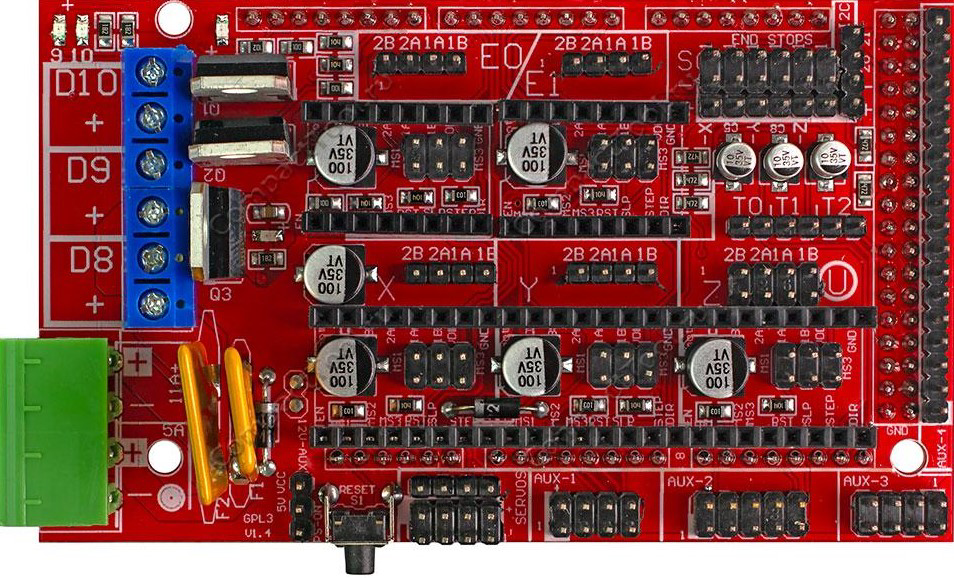
The RAMPS 1.4 Shield (Manufacturer Part ID: RAMPS-1.4-MEGA) is a widely used expansion board designed for 3D printers. It interfaces seamlessly with the Arduino Mega 2560, providing a modular and scalable solution for controlling stepper motors, heaters, fans, and other peripherals required in 3D printing applications. Its compact design and compatibility with various firmware make it a popular choice among hobbyists and professionals alike.
Explore Projects Built with RAMPS 1.4 Shield
 Open Project in Cirkit Designer
 Open Project in Cirkit Designer
 Open Project in Cirkit Designer
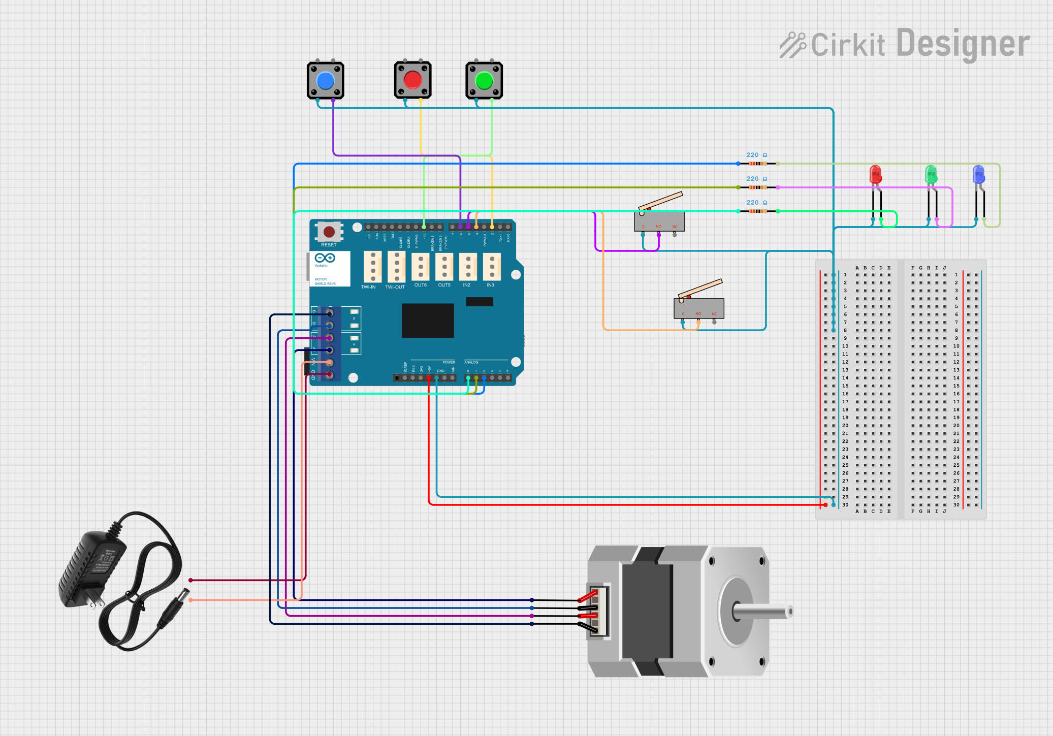 Open Project in Cirkit Designer
Explore Projects Built with RAMPS 1.4 Shield
Open Project in Cirkit DesignerOpen Project in Cirkit DesignerOpen Project in Cirkit DesignerOpen Project in Cirkit DesignerCommon Applications and Use Cases
- 3D printers (e.g., RepRap and similar open-source designs)
- CNC machines
- Laser engravers
- Robotics projects requiring multiple stepper motor control
- Prototyping and educational projects involving motion control
Technical Specifications
Key Technical Details
- Input Voltage: 12V–24V DC (dependent on connected components)
- Stepper Motor Drivers: Supports up to 5 stepper motor drivers (e.g., A4988, DRV8825)
- Heater Outputs: 3 (2 for extruders, 1 for heated bed)
- Fan Outputs: 1 dedicated fan output
- Thermistor Inputs: 3 (for temperature monitoring)
- Endstop Inputs: 6 (3 for minimum and 3 for maximum endstops)
- Communication Interface: I2C, SPI, and UART via Arduino Mega
- Dimensions: 101.5mm x 60.6mm
- Weight: ~50g (without stepper drivers)
Pin Configuration and Descriptions
The RAMPS 1.4 Shield connects directly to the Arduino Mega 2560. Below is a breakdown of its key pin configurations:
Stepper Motor Driver Sockets
| Pin Name | Description |
|---|---|
| VMOT | Motor power supply (12V–24V DC) |
| GND | Ground |
| STEP | Step pulse input for motor movement |
| DIR | Direction control input |
| EN | Enable/disable motor driver |
Heater and Fan Outputs
| Pin Name | Description |
|---|---|
| D10 | Heater 1 (Extruder 1) output |
| D9 | Heater 2 (Extruder 2 or fan) output |
| D8 | Heated bed output |
Thermistor Inputs
| Pin Name | Description |
|---|---|
| T0 | Thermistor input for Extruder 1 |
| T1 | Thermistor input for Extruder 2 |
| T2 | Thermistor input for Heated Bed |
Endstop Inputs
| Pin Name | Description |
|---|---|
| X_MIN | Minimum endstop for X-axis |
| X_MAX | Maximum endstop for X-axis |
| Y_MIN | Minimum endstop for Y-axis |
| Y_MAX | Maximum endstop for Y-axis |
| Z_MIN | Minimum endstop for Z-axis |
| Z_MAX | Maximum endstop for Z-axis |
Usage Instructions
How to Use the RAMPS 1.4 Shield in a Circuit
- Mount the Shield: Place the RAMPS 1.4 Shield on top of an Arduino Mega 2560, ensuring all pins are aligned correctly.
- Install Stepper Drivers: Insert stepper motor drivers (e.g., A4988 or DRV8825) into the designated sockets. Ensure proper orientation by matching the enable pin (EN) with the corresponding pin on the shield.
- Connect Motors and Peripherals:
- Attach stepper motors to the X, Y, Z, and E (extruder) motor outputs.
- Connect heaters, fans, and thermistors to their respective terminals.
- Wire endstops to the appropriate inputs (e.g., X_MIN, Y_MIN, etc.).
- Power the Shield: Connect a 12V–24V DC power supply to the power input terminals. Ensure the power supply matches the voltage requirements of your motors and heaters.
- Upload Firmware: Use a USB cable to connect the Arduino Mega to your computer. Upload compatible firmware (e.g., Marlin, Repetier, or Sprinter) using the Arduino IDE.
- Test the Setup: Verify all connections and test the system using the firmware's control interface.
Important Considerations and Best Practices
- Cooling: Ensure proper cooling for the stepper motor drivers, as they can overheat during operation. Use heatsinks and a cooling fan if necessary.
- Current Adjustment: Adjust the current limit on the stepper drivers to match the specifications of your stepper motors. This prevents overheating and ensures smooth operation.
- Polarity: Double-check the polarity of all connections, especially the power supply, to avoid damaging the shield or connected components.
- Firmware Configuration: Configure the firmware to match your hardware setup (e.g., stepper motor steps per mm, endstop logic, thermistor type).
Example Code for Arduino Mega
Below is an example of how to control a stepper motor connected to the RAMPS 1.4 Shield using the Arduino IDE:
// Example: Basic stepper motor control with RAMPS 1.4 Shield
// This code assumes a stepper motor is connected to the X-axis driver.

#define STEP_PIN 54  // X-axis STEP pin on RAMPS 1.4
#define DIR_PIN 55   // X-axis DIR pin on RAMPS 1.4
#define EN_PIN 38    // Enable pin for all stepper drivers

void setup() {
  pinMode(STEP_PIN, OUTPUT);  // Set STEP pin as output
  pinMode(DIR_PIN, OUTPUT);   // Set DIR pin as output
  pinMode(EN_PIN, OUTPUT);    // Set EN pin as output

  digitalWrite(EN_PIN, LOW);  // Enable the stepper driver
}

void loop() {
  digitalWrite(DIR_PIN, HIGH);  // Set direction to forward
  for (int i = 0; i < 200; i++) {  // Move 200 steps (1 revolution for 1.8° motors)
    digitalWrite(STEP_PIN, HIGH);
    delayMicroseconds(1000);  // Step pulse duration
    digitalWrite(STEP_PIN, LOW);
    delayMicroseconds(1000);  // Step pulse interval
  }
  delay(1000);  // Wait 1 second

  digitalWrite(DIR_PIN, LOW);  // Set direction to reverse
  for (int i = 0; i < 200; i++) {  // Move 200 steps in reverse
    digitalWrite(STEP_PIN, HIGH);
    delayMicroseconds(1000);
    digitalWrite(STEP_PIN, LOW);
    delayMicroseconds(1000);
  }
  delay(1000);  // Wait 1 second
}
Troubleshooting and FAQs
Common Issues and Solutions
Stepper Motors Not Moving:
- Ensure the stepper drivers are properly seated and oriented.
- Verify the current limit on the stepper drivers is set correctly.
- Check the firmware configuration for correct pin assignments.
Overheating Stepper Drivers:
- Install heatsinks and ensure adequate airflow.
- Reduce the current limit on the stepper drivers.
No Power to the Shield:
- Check the power supply connections and ensure the voltage is within the specified range.
- Verify the fuse on the RAMPS 1.4 Shield is intact.
Temperature Readings Are Incorrect:
- Ensure the thermistors are connected to the correct inputs (T0, T1, or T2).
- Verify the thermistor type is correctly configured in the firmware.
FAQs
Can I use the RAMPS 1.4 Shield with other Arduino boards? No, the RAMPS 1.4 Shield is specifically designed for the Arduino Mega 2560 due to its pin layout and number of I/O pins.
What stepper drivers are compatible with the RAMPS 1.4 Shield? The shield supports A4988, DRV8825, and similar stepper motor drivers.
How do I update the firmware? Connect the Arduino Mega to your computer via USB, open the Arduino IDE, and upload the desired firmware (e.g., Marlin).
Can I control multiple extruders with this shield? Yes, the RAMPS 1.4 Shield supports up to two extruders.