Cirkit Designer
Your all-in-one circuit design IDE
Home /
Component Documentation
How to Use MCP4131-103E/P Digital Potentiometer: Examples, Pinouts, and Specs
Introduction
The MCP4131-103E/P is a digital potentiometer manufactured by Microchip. It features 128 wiper steps, allowing for precise adjustment of resistance in electronic circuits through digital control. This component is commonly used in applications such as volume control, sensor calibration, and adjustable power supplies.
Explore Projects Built with MCP4131-103E/P Digital Potentiometer
Teensy 4.1-Based Multi-Channel Potentiometer Interface with 74HC4051 Mux and AMS1117 3.3V Regulator

This circuit features a Teensy 4.1 microcontroller interfaced with a SparkFun 74HC4051 8-channel multiplexer to read multiple rotary potentiometers. The AMS1117 3.3V voltage regulator provides a stable 3.3V supply to the multiplexer and potentiometers, while electrolytic and ceramic capacitors are used for power supply filtering and stabilization.
Teensy 4.1-Based Multi-Channel Analog Input System with Potentiometer Control

This circuit is a multi-channel analog input system that uses a Teensy 4.1 microcontroller to read multiple potentiometers through an 8-channel and a 16-channel multiplexer. The circuit includes voltage regulation using an AMS1117 3.3V regulator and capacitors for power stabilization.
STM32F103C8T6-Based Adjustable Voltage Sensor
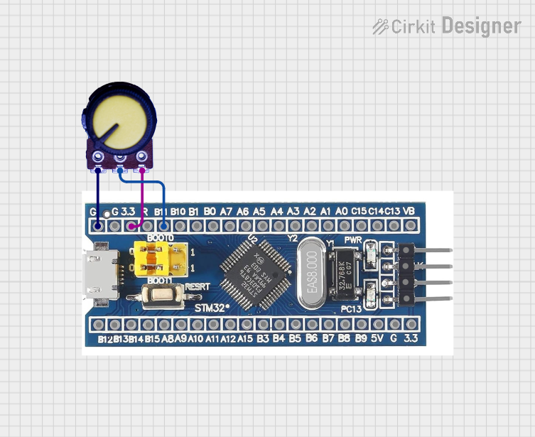
This circuit features an STM32F103C8T6 microcontroller interfaced with a potentiometer. The potentiometer's output is connected to pin B11 of the microcontroller, allowing the microcontroller to read the analog voltage from the potentiometer for further processing or control.
Analog Multiplexer-Based Multi-Potentiometer Input System

This circuit uses a 16-channel analog multiplexer to read the wiper positions of multiple rotary potentiometers, allowing for the selection and measurement of different analog signals. Additionally, an 8-channel multiplexer is used to read the states of multiple pushbuttons, enabling digital input selection.
Explore Projects Built with MCP4131-103E/P Digital Potentiometer
Teensy 4.1-Based Multi-Channel Potentiometer Interface with 74HC4051 Mux and AMS1117 3.3V Regulator
This circuit features a Teensy 4.1 microcontroller interfaced with a SparkFun 74HC4051 8-channel multiplexer to read multiple rotary potentiometers. The AMS1117 3.3V voltage regulator provides a stable 3.3V supply to the multiplexer and potentiometers, while electrolytic and ceramic capacitors are used for power supply filtering and stabilization.
Teensy 4.1-Based Multi-Channel Analog Input System with Potentiometer Control
This circuit is a multi-channel analog input system that uses a Teensy 4.1 microcontroller to read multiple potentiometers through an 8-channel and a 16-channel multiplexer. The circuit includes voltage regulation using an AMS1117 3.3V regulator and capacitors for power stabilization.
STM32F103C8T6-Based Adjustable Voltage Sensor
This circuit features an STM32F103C8T6 microcontroller interfaced with a potentiometer. The potentiometer's output is connected to pin B11 of the microcontroller, allowing the microcontroller to read the analog voltage from the potentiometer for further processing or control.
Analog Multiplexer-Based Multi-Potentiometer Input System
This circuit uses a 16-channel analog multiplexer to read the wiper positions of multiple rotary potentiometers, allowing for the selection and measurement of different analog signals. Additionally, an 8-channel multiplexer is used to read the states of multiple pushbuttons, enabling digital input selection.
Technical Specifications
Key Technical Details
| Parameter | Value |
|---|---|
| Resistance | 10 kΩ |
| Wiper Steps | 128 |
| Supply Voltage (VDD) | 2.7V to 5.5V |
| Current (I_DD) | 1 µA (typical) |
| Interface | SPI |
| Operating Temp | -40°C to +125°C |
| Package | PDIP-8 |
Pin Configuration and Descriptions
| Pin No. | Pin Name | Description |
|---|---|---|
| 1 | CS | Chip Select (Active Low) |
| 2 | SCK | Serial Clock Input |
| 3 | SI | Serial Data Input |
| 4 | VSS | Ground |
| 5 | PW0 | Terminal 0 of Potentiometer |
| 6 | PW1 | Terminal 1 of Potentiometer |
| 7 | P0A | Wiper Terminal |
| 8 | VDD | Positive Supply Voltage |
Usage Instructions
How to Use the Component in a Circuit
- Power Supply: Connect the VDD pin to a power supply (2.7V to 5.5V) and the VSS pin to ground.
- SPI Interface: Connect the CS, SCK, and SI pins to the corresponding pins on your microcontroller or SPI master device.
- Potentiometer Terminals: Connect PW0 and PW1 to the points in your circuit where you need variable resistance. The wiper terminal (P0A) will provide the adjustable resistance.
Important Considerations and Best Practices
- Decoupling Capacitor: Place a 0.1 µF decoupling capacitor close to the VDD pin to filter out noise.
- SPI Communication: Ensure proper SPI communication settings (clock polarity, phase, and speed) as per the MCP4131 datasheet.
- Wiper Position: The wiper position is controlled by an 8-bit command sent via SPI. Ensure correct command format for desired resistance.
Example Circuit with Arduino UNO
#include <SPI.h>

const int CS_PIN = 10; // Chip Select pin for MCP4131

void setup() {
  pinMode(CS_PIN, OUTPUT);
  digitalWrite(CS_PIN, HIGH); // Ensure CS is high
  SPI.begin();
}

void loop() {
  setPotentiometer(64); // Set wiper to mid position (64 out of 128)
  delay(1000);
}

void setPotentiometer(byte value) {
  digitalWrite(CS_PIN, LOW); // Select MCP4131
  SPI.transfer(0x00); // Command byte for wiper position
  SPI.transfer(value); // Wiper position value
  digitalWrite(CS_PIN, HIGH); // Deselect MCP4131
}
Troubleshooting and FAQs
Common Issues Users Might Face
No Response from MCP4131:
- Solution: Check the SPI connections and ensure the CS pin is correctly toggled.
Incorrect Resistance:
- Solution: Verify the wiper position command and ensure the value sent is within the 0-127 range.
Noise in Output:
- Solution: Add a decoupling capacitor close to the VDD pin to filter out power supply noise.
FAQs
Q1: Can I use the MCP4131 with a 3.3V microcontroller?
- A1: Yes, the MCP4131 operates within a supply voltage range of 2.7V to 5.5V, making it compatible with 3.3V systems.
Q2: How do I reset the wiper position to default?
- A2: The wiper position can be reset by sending a specific command via SPI. Refer to the MCP4131 datasheet for detailed command instructions.
Q3: Can I use multiple MCP4131 devices on the same SPI bus?
- A3: Yes, you can use multiple MCP4131 devices on the same SPI bus by assigning a unique CS pin for each device.
This documentation provides a comprehensive guide to using the MCP4131-103E/P digital potentiometer. For further details, refer to the official datasheet provided by Microchip.