How to Use ESP8266 ESP-12F WiFi Module: Examples, Pinouts, and Specs
Introduction
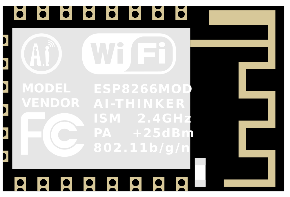
The ESP8266 ESP-12F WiFi Module is a highly integrated chip designed for the needs of a new connected world. It offers a complete and self-contained Wi-Fi networking solution, allowing it to either host the application or offload all Wi-Fi networking functions from another application processor. Common applications for the ESP8266 ESP-12F include smart home devices, wireless sensor networks, and other IoT solutions.
Explore Projects Built with ESP8266 ESP-12F WiFi Module


Explore Projects Built with ESP8266 ESP-12F WiFi Module
Technical Specifications
Key Technical Details
- Wi-Fi Protocols: 802.11 b/g/n
- Frequency Range: 2.4 GHz - 2.5 GHz
- Operating Voltage: 3.0V - 3.6V
- Operating Current: Average value: 80 mA
- Peak Current: Up to 300 mA
- Flash Memory: 4MB
- I/O Pins: 22
- Serial Communication: UART, SPI, I2C
- Operating Temperature: -40°C to 125°C
Pin Configuration and Descriptions
| Pin Number | Name | Description |
|---|---|---|
| 1 | GND | Ground |
| 2 | GPIO15 | General Purpose I/O |
| 3 | GPIO2 | General Purpose I/O, also used for boot mode selection |
| 4 | GPIO0 | General Purpose I/O, also used for boot mode selection |
| 5 | GPIO4 | General Purpose I/O |
| 6 | VDDA | Analog Power 3.0V - 3.6V |
| 7 | TOUT | ADC Channel (Analog Input) |
| 8 | CH_PD | Chip Power-Down Pin. Active high. |
| 9 | GPIO5 | General Purpose I/O |
| 10 | GPIO14 | General Purpose I/O |
| 11 | GPIO12 | General Purpose I/O |
| 12 | GPIO13 | General Purpose I/O |
| 13 | VDDPST | Digital Power 3.0V - 3.6V |
| 14 | GPIO16 | General Purpose I/O |
| 15 | GPIO17 | General Purpose I/O |
| 16 | GPIO9 | General Purpose I/O |
| 17 | GPIO10 | General Purpose I/O |
| 18 | SDIO_CLK | SDIO Clock |
| 19 | SDIO_DATA_0 | SDIO Data 0 |
| 20 | SDIO_DATA_1 | SDIO Data 1 |
| 21 | SDIO_DATA_2 | SDIO Data 2 |
| 22 | SDIO_DATA_3 | SDIO Data 3 |
| 23 | SDIO_CMD | SDIO Command |
| 24 | GPIO11 | General Purpose I/O |
| 25 | RXD | UART Receive Pin |
| 26 | TXD | UART Transmit Pin |
| 27 | RESET | Reset Pin (Active low) |
| 28 | VCC | Power Supply 3.0V - 3.6V |
Usage Instructions
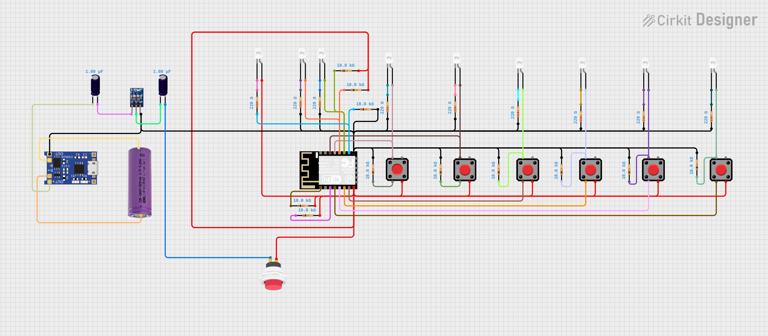
How to Use the Component in a Circuit
- Power Supply: Connect a 3.3V power supply to the VCC and GND pins. Do not exceed 3.6V to avoid damaging the module.
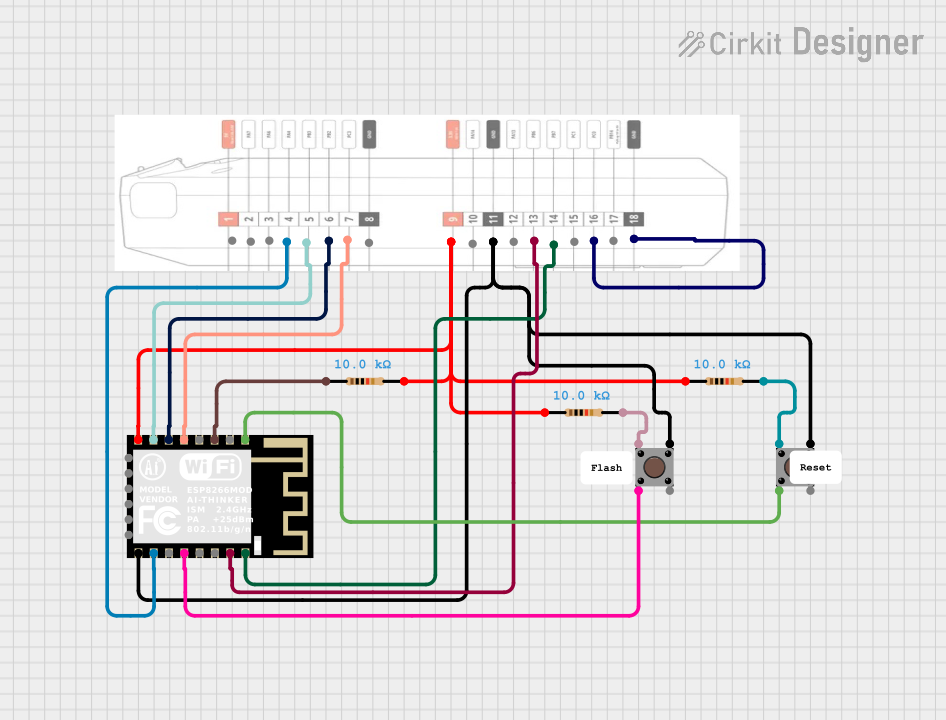
- Boot Mode Selection: To boot from flash, connect GPIO0 to GND, and GPIO2 to VCC through a pull-up resistor.
- Serial Communication: Connect the RXD and TXD pins to a USB-to-Serial converter to communicate with the module via UART.
- Programming: Use the provided GPIO pins to interface with sensors, actuators, or other peripherals as required by your application.
- Antenna: The module comes with a built-in PCB antenna. Ensure that the antenna area is not obstructed for optimal wireless performance.
Important Considerations and Best Practices
- Always use a stable 3.3V power supply with sufficient current capability (at least 500 mA).
- Use a logic level converter if interfacing with 5V logic levels to prevent damage to the module.
- Avoid placing the module near metal objects or surfaces that can interfere with the Wi-Fi signal.
- Ensure that the CH_PD pin is pulled high during normal operation.
- For ADC readings, note that the TOUT pin can only accept a maximum of 1V input voltage.
Troubleshooting and FAQs
Common Issues
- Module Does Not Power On: Check the power supply and connections to the VCC and GND pins. Ensure CH_PD is pulled high.
- Cannot Connect to Wi-Fi: Verify the antenna is not obstructed and the Wi-Fi credentials are correct.
- Serial Communication Failure: Ensure that the baud rate is set correctly and the RXD/TXD connections are not reversed.
Solutions and Tips for Troubleshooting
- If the module is not responding, try pulling the RESET pin low to reset the module.
- For Wi-Fi connectivity issues, try moving the module closer to the router or access point to rule out signal strength problems.
- Use external pull-up resistors on the GPIO0 and GPIO2 pins during boot to ensure proper boot mode selection.
FAQs
Q: Can the ESP8266 ESP-12F be used with an Arduino? A: Yes, it can be used with an Arduino by connecting it via the UART interface and using the appropriate AT commands or flashing it with custom firmware.
Q: What is the maximum voltage that can be applied to the I/O pins? A: The maximum voltage for the I/O pins is 3.6V. Exceeding this voltage can damage the module.
Q: How do I flash custom firmware onto the ESP8266 ESP-12F? A: Custom firmware can be flashed using the UART interface and a USB-to-Serial converter. The module must be put into flash mode by setting GPIO0 to GND during power-up.
Q: Can the ESP8266 ESP-12F act as a standalone microcontroller? A: Yes, the ESP8266 ESP-12F has built-in processing capabilities and can run applications without the need for an external microcontroller.
Example Code for Arduino UNO
#include <ESP8266WiFi.h>

// Replace with your network credentials
const char* ssid = "your_SSID";
const char* password = "your_PASSWORD";

void setup() {
  Serial.begin(115200);
  // Connect to Wi-Fi
  WiFi.begin(ssid, password);
  while (WiFi.status() != WL_CONNECTED) {
    delay(500);
    Serial.println("Connecting to WiFi...");
  }
  Serial.println("Connected to WiFi");
}

void loop() {
  // Your code here
}
Note: This example assumes that the ESP8266 ESP-12F has been flashed with firmware that allows it to be programmed using the Arduino IDE. The ESP8266 library must be installed in the Arduino IDE to use the ESP8266WiFi class.