How to Use RS422 to TTL Converter: Examples, Pinouts, and Specs
Introduction
The RS422 to TTL Converter is a device designed to bridge the gap between RS422 differential signals and TTL (Transistor-Transistor Logic) levels. RS422 is a robust communication standard commonly used in industrial and long-distance applications due to its noise immunity and differential signaling. TTL, on the other hand, is a logic level standard used in microcontrollers, digital circuits, and embedded systems.
This converter enables seamless communication between devices that operate on these two different signaling standards. It is particularly useful in scenarios where industrial equipment (using RS422) needs to interface with microcontrollers, such as Arduino, Raspberry Pi, or other TTL-based systems.
Explore Projects Built with RS422 to TTL Converter


Explore Projects Built with RS422 to TTL Converter
Common Applications and Use Cases
- Interfacing industrial RS422 devices with microcontrollers or TTL-based systems.
- Data acquisition systems requiring communication between sensors and controllers.
- Robotics and automation systems where RS422 devices need to communicate with TTL logic circuits.
- Long-distance communication where RS422 is used for its noise immunity, but the receiving device operates on TTL levels.
Technical Specifications
Key Technical Details
- Input Signal Standard: RS422 (differential signaling)
- Output Signal Standard: TTL (0V to 5V logic levels)
- Operating Voltage: 3.3V or 5V (depending on the model)
- Baud Rate: Up to 1 Mbps (varies by model)
- Input Impedance: Typically 120Ω (termination resistor may be included)
- Output Current: Up to 20mA (sufficient to drive TTL inputs)
- Operating Temperature: -40°C to +85°C
- Connector Type: Screw terminals or DB9 for RS422 input, pin headers for TTL output
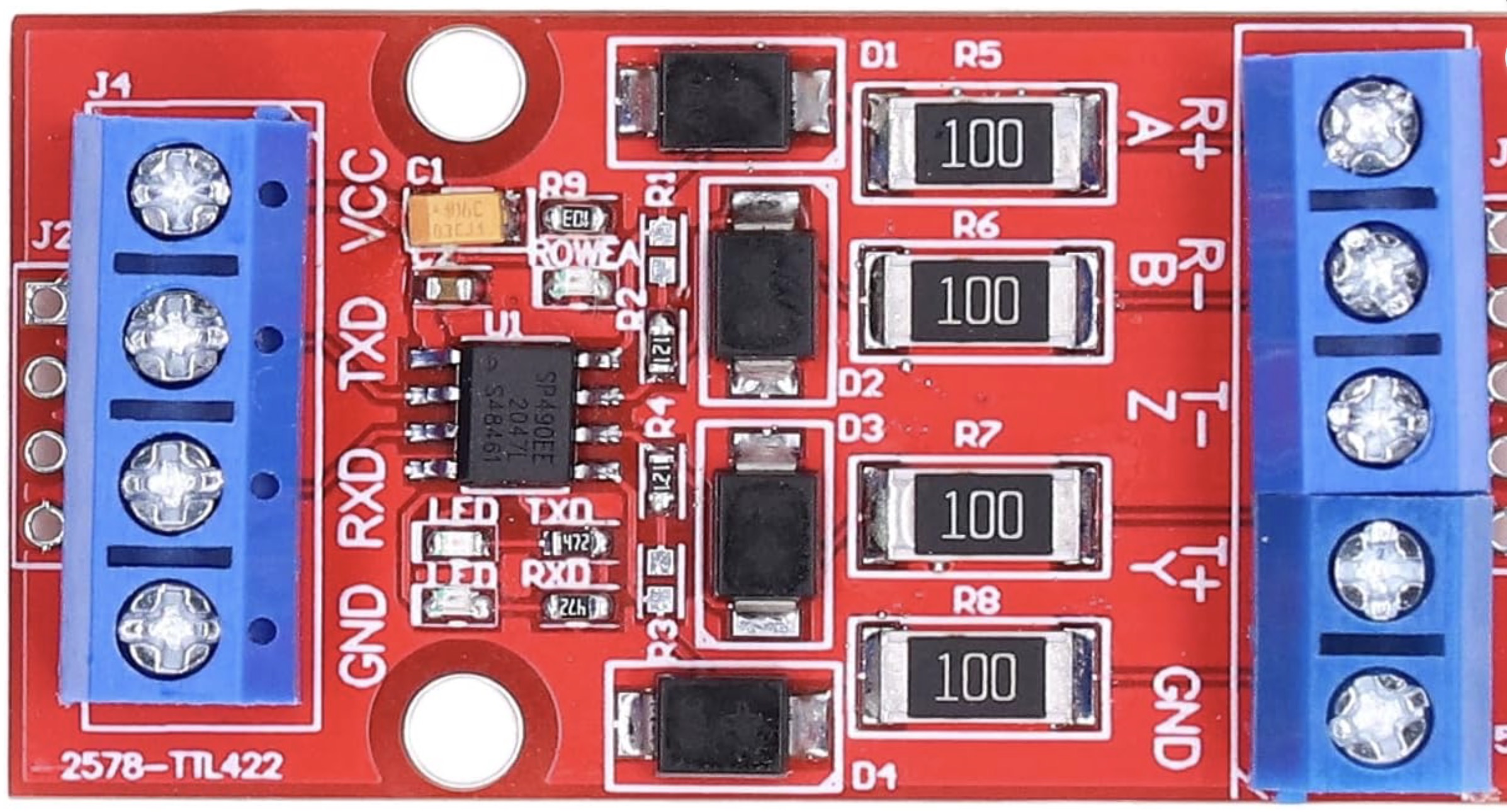
Pin Configuration and Descriptions
RS422 Input Side
| Pin Name | Description |
|---|---|
| A | Non-inverting RS422 input (positive) |
| B | Inverting RS422 input (negative) |
| GND | Ground reference for RS422 signals |
TTL Output Side
| Pin Name | Description |
|---|---|
| VCC | Power supply input (3.3V or 5V) |
| GND | Ground reference |
| TX | TTL output signal (transmitted data) |
| RX | TTL input signal (received data) |
Usage Instructions
How to Use the Component in a Circuit
- Power the Converter: Connect the VCC pin to a 3.3V or 5V power source (depending on the model) and the GND pin to the ground.
- Connect RS422 Signals: Attach the RS422 signal lines to the A and B pins. Ensure proper polarity:
- A is the non-inverting input (positive).
- B is the inverting input (negative).
- Connect TTL Signals: Connect the TX pin to the RX pin of your microcontroller (e.g., Arduino) and the RX pin to the TX pin of your microcontroller.
- Termination Resistor: If the RS422 line is not terminated, add a 120Ω resistor across the A and B pins to prevent signal reflections.
Important Considerations and Best Practices
- Signal Grounding: Ensure that the ground of the RS422 device is connected to the ground of the converter to maintain a common reference.
- Baud Rate Matching: Configure the baud rate of the RS422 device and the TTL device to match for proper communication.
- Cable Length: RS422 supports long cable lengths (up to 1200 meters), but ensure the cable is twisted pair for noise immunity.
- Voltage Compatibility: Verify that the TTL output voltage level (3.3V or 5V) matches the input requirements of the connected TTL device.
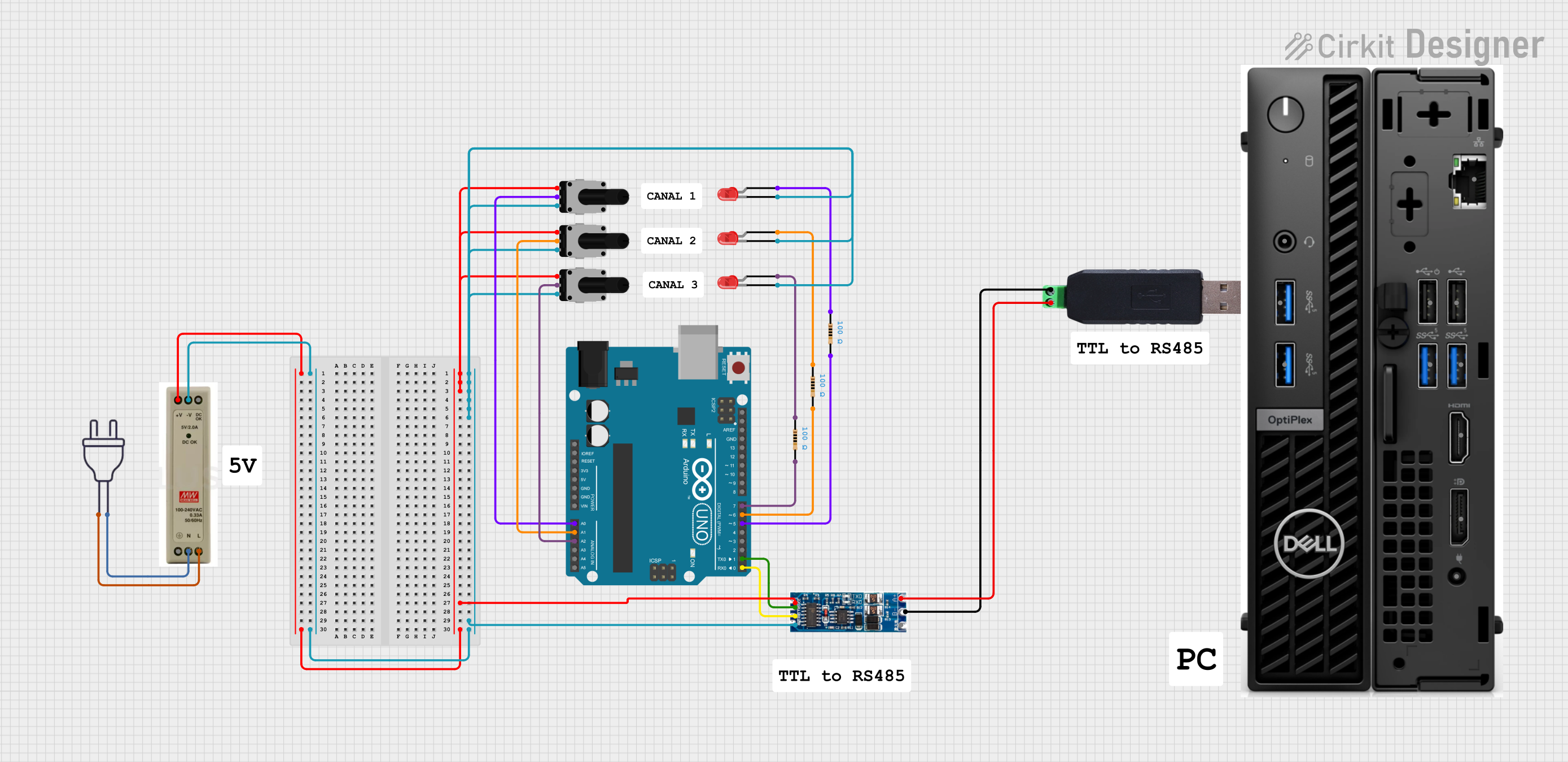
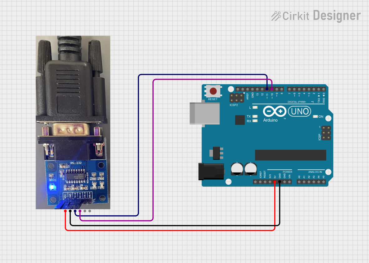
Example: Connecting to an Arduino UNO
Below is an example of how to connect the RS422 to TTL Converter to an Arduino UNO and read data.
Circuit Diagram
- RS422 A and B pins connect to the RS422 device.
- TX pin of the converter connects to Arduino's RX pin (pin 0).
- RX pin of the converter connects to Arduino's TX pin (pin 1).
- VCC and GND of the converter connect to the Arduino's 5V and GND pins, respectively.
Arduino Code Example
// Example code to read data from an RS422 device using the RS422 to TTL Converter
// and display it on the Serial Monitor.

void setup() {
  Serial.begin(9600); // Initialize Serial Monitor at 9600 baud
  Serial1.begin(9600); // Initialize RS422 communication at 9600 baud
  // Note: Serial1 is used for hardware serial communication on some Arduino boards.
}

void loop() {
  // Check if data is available from the RS422 device
  if (Serial1.available()) {
    char data = Serial1.read(); // Read one byte of data
    Serial.print("Received: "); // Print the received data to the Serial Monitor
    Serial.println(data);
  }
}
Note: On Arduino UNO, hardware serial (Serial1) is not available. Use SoftwareSerial for RS422 communication if needed.
Troubleshooting and FAQs
Common Issues and Solutions
No Data Received on TTL Side
- Verify that the RS422 device is powered and transmitting data.
- Check the polarity of the RS422 signals (A and B).
- Ensure the baud rate of the RS422 device matches the TTL device.
Corrupted Data
- Check for proper grounding between the RS422 device and the converter.
- Ensure the RS422 cable is twisted pair and shielded to minimize noise.
- Verify that the termination resistor (120Ω) is installed if required.
Converter Not Powering On
- Confirm that the VCC pin is connected to the correct voltage (3.3V or 5V).
- Check for loose connections or damaged wires.
FAQs
Q: Can I use this converter for RS485 communication?
A: No, this converter is specifically designed for RS422 signals. RS485 uses a different protocol and may require a dedicated RS485 to TTL converter.
Q: What is the maximum baud rate supported?
A: The maximum baud rate is typically 1 Mbps, but refer to the specific model's datasheet for exact details.
Q: Can I use this converter with a 3.3V microcontroller?
A: Yes, as long as the converter supports 3.3V operation. Check the model specifications to confirm compatibility.
This documentation provides a comprehensive guide to understanding, using, and troubleshooting the RS422 to TTL Converter. For further assistance, consult the manufacturer's datasheet or technical support.