How to Use Battery Shunt: Examples, Pinouts, and Specs
Introduction
A battery shunt is a precision resistor designed to measure the current flowing in and out of a battery. By providing a low-resistance path for current, it enables accurate monitoring of battery performance. The voltage drop across the shunt is proportional to the current flow, which can then be measured and used to calculate the current. Battery shunts are essential in applications requiring precise current monitoring, such as battery management systems (BMS), renewable energy systems, and electric vehicles.
Explore Projects Built with Battery Shunt


Explore Projects Built with Battery Shunt
Common Applications and Use Cases
- Battery management systems (BMS) for monitoring charge and discharge currents
- Renewable energy systems (e.g., solar or wind power setups)
- Electric vehicles and hybrid systems
- Industrial power systems
- Backup power systems and uninterruptible power supplies (UPS)
Technical Specifications
Below are the key technical details for the Custom Battery Shunt:
| Parameter | Value |
|---|---|
| Manufacturer | Custom |
| Manufacturer Part ID | Custom |
| Resistance Value | 50 µΩ (micro-ohms) |
| Maximum Current Rating | 300 A |
| Voltage Drop Range | 0–75 mV |
| Accuracy | ±0.25% |
| Operating Temperature | -40°C to +85°C |
| Material | Manganin (low TCR alloy) |
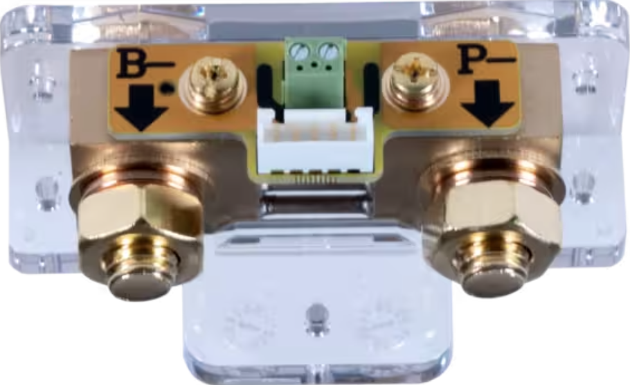
Pin Configuration and Descriptions
The battery shunt typically has two main connection points and two sense terminals:
| Pin/Terminal | Description |
|---|---|
| Current Input | Connects to the positive or negative terminal of the battery for current flow. |
| Current Output | Connects to the load or charging system. |
| Sense+ | High-side voltage sense terminal for measuring voltage drop across the shunt. |
| Sense- | Low-side voltage sense terminal for measuring voltage drop across the shunt. |
Usage Instructions
How to Use the Battery Shunt in a Circuit
Placement in the Circuit:
- Place the shunt in series with the battery's positive or negative terminal.
- Ensure the current input and output terminals are connected correctly to avoid polarity issues.
Voltage Measurement:
- Use a high-precision voltmeter or an analog-to-digital converter (ADC) to measure the voltage drop across the sense terminals (Sense+ and Sense-).
- The measured voltage drop is proportional to the current flowing through the shunt, calculated using Ohm's Law:
[ I = \frac{V}{R} ]
where ( I ) is the current, ( V ) is the voltage drop, and ( R ) is the shunt resistance.
Connection to a Microcontroller:
- Connect the Sense+ and Sense- terminals to the ADC pins of a microcontroller (e.g., Arduino UNO) for real-time current monitoring.
- Use a differential amplifier if the voltage drop is too small for direct ADC measurement.
Power Dissipation:
- Ensure the shunt's power dissipation does not exceed its rated capacity. Power dissipation can be calculated as:
[ P = I^2 \times R ]
where ( P ) is the power, ( I ) is the current, and ( R ) is the resistance.
- Ensure the shunt's power dissipation does not exceed its rated capacity. Power dissipation can be calculated as:
Important Considerations and Best Practices
- Accuracy: Use shielded cables for the sense terminals to minimize noise and improve measurement accuracy.
- Thermal Management: Ensure proper ventilation or cooling to prevent overheating, especially at high currents.
- Calibration: Periodically calibrate the shunt to maintain accuracy over time.
- Safety: Avoid exceeding the maximum current rating to prevent damage to the shunt or the circuit.
Example: Connecting to an Arduino UNO
Below is an example of how to connect the battery shunt to an Arduino UNO for current measurement:
Circuit Diagram
- Connect the Sense+ terminal to the Arduino's analog input pin (e.g., A0).
- Connect the Sense- terminal to the Arduino's ground (GND).
- Use a voltage divider or amplifier if the voltage drop exceeds the ADC input range.
Arduino Code
// Battery Shunt Current Measurement Example
// Assumes a 50 µΩ shunt with a maximum voltage drop of 75 mV

const int shuntPin = A0;  // Analog pin connected to Sense+ terminal
const float shuntResistance = 0.00005;  // Shunt resistance in ohms (50 µΩ)
const float adcReferenceVoltage = 5.0;  // Arduino ADC reference voltage (5V)
const int adcResolution = 1024;         // 10-bit ADC resolution

void setup() {
  Serial.begin(9600);  // Initialize serial communication
}

void loop() {
  int adcValue = analogRead(shuntPin);  // Read ADC value
  float voltageDrop = (adcValue * adcReferenceVoltage) / adcResolution;
  // Calculate current using Ohm's Law: I = V / R
  float current = voltageDrop / shuntResistance;

  // Print the measured current to the Serial Monitor
  Serial.print("Current: ");
  Serial.print(current, 2);  // Print current with 2 decimal places
  Serial.println(" A");

  delay(1000);  // Wait 1 second before the next reading
}
Troubleshooting and FAQs
Common Issues and Solutions
Inaccurate Current Measurements:
- Cause: Electrical noise or poor connections.
- Solution: Use shielded cables for the sense terminals and ensure secure connections.
Overheating of the Shunt:
- Cause: Exceeding the maximum current rating.
- Solution: Verify the current does not exceed the shunt's rated capacity.
No Voltage Drop Detected:
- Cause: Incorrect wiring or damaged shunt.
- Solution: Double-check the wiring and test the shunt with a known current source.
ADC Saturation on Microcontroller:
- Cause: Voltage drop exceeds the ADC input range.
- Solution: Use a voltage divider or amplifier to scale the voltage drop.
FAQs
Q: Can I use the battery shunt for AC current measurement?
A: Battery shunts are primarily designed for DC current measurement. For AC applications, additional circuitry (e.g., rectifiers) may be required.
Q: How do I protect the shunt from overcurrent?
A: Use a fuse or circuit breaker in series with the shunt to prevent damage from overcurrent conditions.
Q: What is the typical lifespan of a battery shunt?
A: With proper usage and within rated specifications, a battery shunt can last for decades without significant degradation.
Q: Can I use the shunt with high-voltage batteries?
A: Yes, but ensure the sense terminals are isolated and rated for the battery's voltage to avoid safety hazards.