How to Use BD135 NPN: Examples, Pinouts, and Specs
Introduction
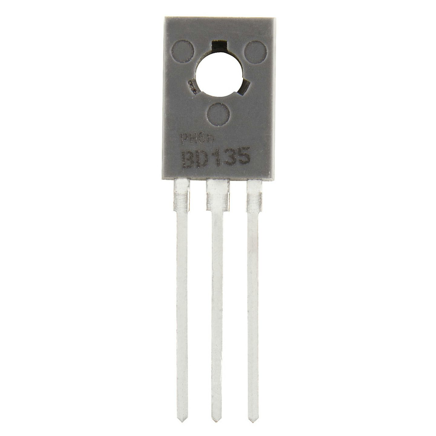
The BD135 is a general-purpose NPN bipolar junction transistor (BJT) designed for amplification and switching applications. It is widely used in audio amplifiers, motor drivers, and other medium-power electronic circuits. With a maximum collector current of 1.5A and a maximum collector-emitter voltage of 45V, the BD135 is a versatile and reliable component for various applications.
Explore Projects Built with BD135 NPN
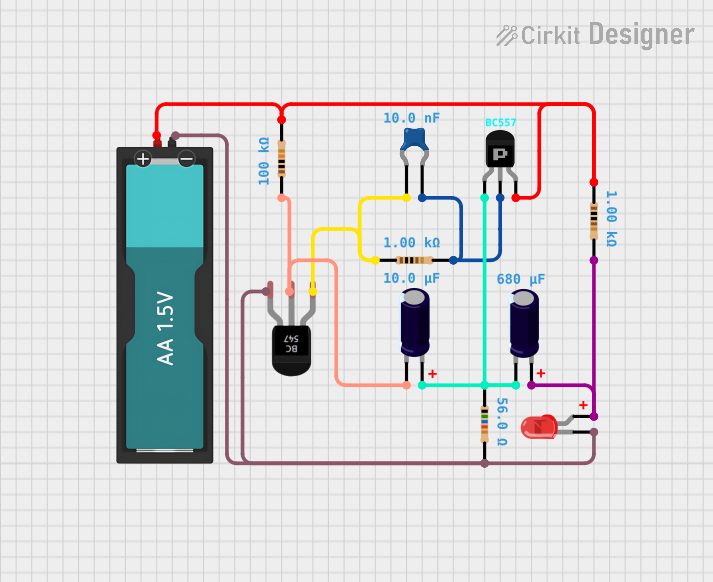

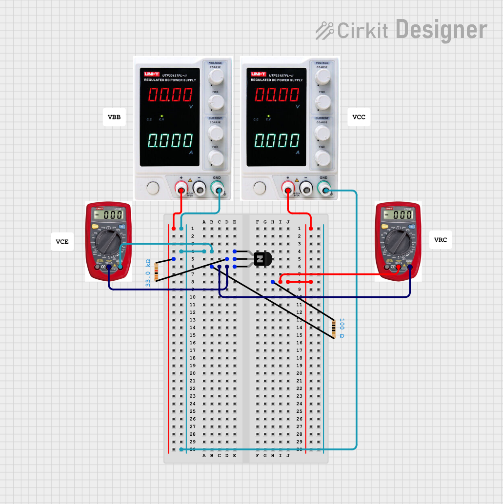

Explore Projects Built with BD135 NPN
Common Applications and Use Cases
- Audio signal amplification
- Motor control circuits
- Switching low to medium power loads
- Voltage regulation circuits
- General-purpose amplification in analog circuits
Technical Specifications
Below are the key technical details of the BD135 transistor:
| Parameter | Value |
|---|---|
| Transistor Type | NPN |
| Maximum Collector-Emitter Voltage (Vce) | 45V |
| Maximum Collector-Base Voltage (Vcb) | 45V |
| Maximum Emitter-Base Voltage (Veb) | 5V |
| Maximum Collector Current (Ic) | 1.5A |
| Maximum Power Dissipation (Ptot) | 12.5W |
| DC Current Gain (hFE) | 25 to 250 |
| Transition Frequency (fT) | 190 MHz |
| Operating Temperature Range | -55°C to +150°C |
| Package Type | TO-126 |
Pin Configuration and Descriptions
The BD135 transistor comes in a TO-126 package with three pins. The pin configuration is as follows:
| Pin Number | Pin Name | Description |
|---|---|---|
| 1 | Emitter (E) | Current flows out of this pin. |
| 2 | Collector (C) | Current flows into this pin. |
| 3 | Base (B) | Controls the transistor's operation. |
Below is the pinout diagram for the BD135 (front view of the TO-126 package):
   _______
  |       |
  |       |
  |   C   |  Pin 2: Collector
  |   B   |  Pin 3: Base
  |   E   |  Pin 1: Emitter
  |_______|
Usage Instructions
How to Use the BD135 in a Circuit
Biasing the Transistor:
- To use the BD135 as a switch, apply a small current to the base pin (B) to control a larger current between the collector (C) and emitter (E).
- For amplification, ensure the transistor is properly biased in the active region.
Base Resistor:
- Always use a base resistor to limit the current flowing into the base pin. The value of the resistor can be calculated using Ohm's law: [ R_b = \frac{V_{in} - V_{be}}{I_b} ] where ( V_{in} ) is the input voltage, ( V_{be} ) is the base-emitter voltage (typically 0.7V for the BD135), and ( I_b ) is the desired base current.
Heat Dissipation:
- The BD135 can dissipate up to 12.5W of power. If operating near this limit, attach a heatsink to prevent overheating.
Connection Example:
- Below is an example of using the BD135 to drive a motor:
+12V ---- Motor ---- Collector (C)
                  |
                  |
                 Emitter (E) ---- GND
                  |
                  |
                 Base (B) ---- Resistor ---- Microcontroller Pin
Arduino Example Code
The following code demonstrates how to use the BD135 to control a motor with an Arduino UNO:
// Define the pin connected to the BD135 base
const int transistorBasePin = 9;

void setup() {
  // Set the transistor base pin as an output
  pinMode(transistorBasePin, OUTPUT);
}

void loop() {
  // Turn the motor ON by sending a HIGH signal to the transistor base
  digitalWrite(transistorBasePin, HIGH);
  delay(2000); // Keep the motor ON for 2 seconds

  // Turn the motor OFF by sending a LOW signal to the transistor base
  digitalWrite(transistorBasePin, LOW);
  delay(2000); // Keep the motor OFF for 2 seconds
}
Note: Ensure the base resistor is properly calculated to limit the current from the Arduino pin to the BD135 base.
Important Considerations and Best Practices
- Voltage and Current Limits: Do not exceed the maximum voltage (45V) or current (1.5A) ratings to avoid damaging the transistor.
- Heat Management: Use a heatsink if the transistor operates at high power levels.
- Base Resistor: Always include a base resistor to prevent excessive current from damaging the transistor or the control circuit.
Troubleshooting and FAQs
Common Issues and Solutions
Transistor Overheating:
- Cause: Operating near the maximum power dissipation without a heatsink.
- Solution: Attach a heatsink to the BD135 to improve heat dissipation.
No Output Current:
- Cause: Insufficient base current or missing base resistor.
- Solution: Verify the base resistor value and ensure the base current is sufficient to drive the load.
Low Amplification:
- Cause: Incorrect biasing or low DC current gain (hFE).
- Solution: Check the biasing circuit and ensure the transistor is operating in the active region.
Transistor Not Switching Properly:
- Cause: Base current too low or incorrect connections.
- Solution: Verify the circuit connections and increase the base current if necessary.
FAQs
Q1: Can the BD135 be used for high-frequency applications?
A1: Yes, the BD135 has a transition frequency (( f_T )) of 190 MHz, making it suitable for some high-frequency applications.
Q2: What is the difference between the BD135 and BD139?
A2: The BD139 is a higher-power variant of the BD135, with similar characteristics but a higher maximum collector-emitter voltage (80V).
Q3: Can I use the BD135 without a heatsink?
A3: Yes, but only if the power dissipation is well below 12.5W. For higher power levels, a heatsink is recommended.
Q4: What is the typical base-emitter voltage (( V_{be} )) of the BD135?
A4: The typical ( V_{be} ) is around 0.7V when the transistor is conducting.