How to Use Core1262 LF/HF LoRa SPI Module: Examples, Pinouts, and Specs
Introduction
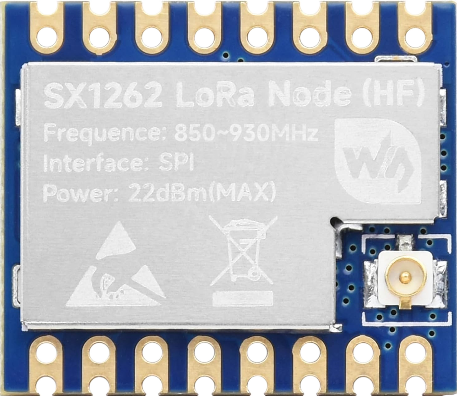
The Core1262 LF/HF LoRa Module by UeeKKoo is a low-power, long-range wireless communication module designed for IoT and telemetry applications. It leverages LoRa (Long Range) technology to enable data transmission over distances of several kilometers, even in environments with significant obstacles or interference. The module operates in both LF (Low Frequency) and HF (High Frequency) bands, making it versatile for various regional frequency regulations. Its SPI interface ensures seamless integration with microcontrollers, making it ideal for applications requiring reliable, low-power, and long-range communication.
Explore Projects Built with Core1262 LF/HF LoRa SPI Module

Explore Projects Built with Core1262 LF/HF LoRa SPI Module
Common Applications
- Smart agriculture (e.g., soil moisture monitoring, weather stations)
- Industrial IoT (e.g., machine monitoring, predictive maintenance)
- Smart cities (e.g., parking sensors, waste management)
- Home automation (e.g., security systems, energy monitoring)
- Remote telemetry and environmental monitoring
Technical Specifications
Key Technical Details
| Parameter | Value |
|---|---|
| Manufacturer | UeeKKoo |
| Part ID | Core1262 LF/HF LoRa Module |
| Frequency Bands | LF (433 MHz), HF (868 MHz/915 MHz) |
| Modulation Technique | LoRa (Long Range) |
| Communication Interface | SPI |
| Supply Voltage | 1.8V to 3.7V |
| Operating Current | 10 mA (typical during transmission) |
| Sleep Current | < 1 µA |
| Output Power | Up to +22 dBm |
| Sensitivity | -137 dBm |
| Operating Temperature | -40°C to +85°C |
| Dimensions | 16 mm x 16 mm x 2.5 mm |
Pin Configuration and Descriptions
| Pin Number | Pin Name | Description |
|---|---|---|
| 1 | VCC | Power supply input (1.8V to 3.7V) |
| 2 | GND | Ground |
| 3 | SCK | SPI Clock |
| 4 | MISO | SPI Master-In-Slave-Out |
| 5 | MOSI | SPI Master-Out-Slave-In |
| 6 | NSS | SPI Chip Select (Active Low) |
| 7 | DIO0 | Digital I/O Pin 0 (Interrupt/Status) |
| 8 | DIO1 | Digital I/O Pin 1 (Optional Interrupt) |
| 9 | RESET | Module Reset (Active Low) |
| 10 | ANT | Antenna Connection |
Usage Instructions
How to Use the Core1262 LF/HF LoRa Module in a Circuit
- Power Supply: Connect the VCC pin to a regulated power source (1.8V to 3.7V) and the GND pin to the ground of your circuit.
- SPI Interface: Connect the SCK, MISO, MOSI, and NSS pins to the corresponding SPI pins of your microcontroller.
- Antenna: Attach a suitable antenna to the ANT pin for optimal signal transmission and reception.
- Reset: Use the RESET pin to initialize the module during startup or after a fault.
- Digital I/O: Use the DIO0 and DIO1 pins for interrupt handling or status monitoring.
Important Considerations and Best Practices
- Antenna Selection: Use an antenna tuned to the operating frequency (e.g., 433 MHz or 868 MHz) for maximum range and performance.
- Power Supply: Ensure a stable and noise-free power supply to avoid communication errors.
- SPI Configuration: Configure the SPI interface on your microcontroller to match the module's settings (e.g., clock polarity and phase).
- Regulatory Compliance: Verify that the operating frequency complies with local regulations (e.g., 433 MHz in Europe, 915 MHz in the US).
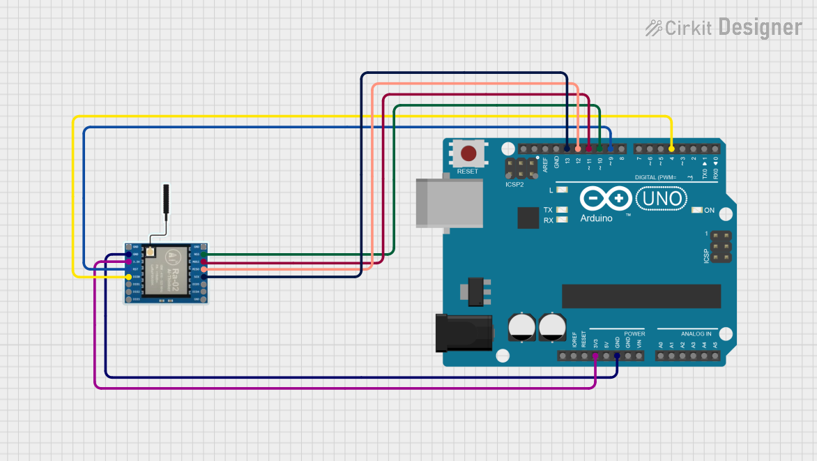
Example: Connecting to an Arduino UNO
Below is an example of how to connect the Core1262 module to an Arduino UNO and send a simple LoRa message.
Wiring Diagram
| Core1262 Pin | Arduino UNO Pin |
|---|---|
| VCC | 3.3V |
| GND | GND |
| SCK | D13 |
| MISO | D12 |
| MOSI | D11 |
| NSS | D10 |
| RESET | D9 |
| DIO0 | D2 |
Arduino Code Example
#include <SPI.h>
#include <LoRa.h> // Include the LoRa library

#define NSS_PIN 10  // SPI Chip Select
#define RESET_PIN 9 // Reset pin
#define DIO0_PIN 2  // Interrupt pin

void setup() {
  // Initialize serial communication for debugging
  Serial.begin(9600);
  while (!Serial);

  // Initialize LoRa module
  Serial.println("Initializing LoRa...");
  LoRa.setPins(NSS_PIN, RESET_PIN, DIO0_PIN); // Set module pins

  if (!LoRa.begin(868E6)) { // Set frequency to 868 MHz
    Serial.println("LoRa initialization failed!");
    while (1);
  }
  Serial.println("LoRa initialized successfully!");
}

void loop() {
  // Send a test message
  Serial.println("Sending message...");
  LoRa.beginPacket();
  LoRa.print("Hello, LoRa!");
  LoRa.endPacket();

  delay(5000); // Wait 5 seconds before sending the next message
}
Troubleshooting and FAQs
Common Issues and Solutions
No Communication with the Module
- Cause: Incorrect SPI wiring or configuration.
- Solution: Double-check the SPI connections and ensure the SPI settings (clock polarity, phase) match the module's requirements.
Poor Signal Range
- Cause: Improper antenna or environmental interference.
- Solution: Use a properly tuned antenna and test in an open area with minimal obstacles.
Module Not Responding
- Cause: Insufficient power supply or incorrect reset handling.
- Solution: Ensure the power supply is stable and toggle the RESET pin to reinitialize the module.
Interference with Other Devices
- Cause: Operating frequency conflicts with nearby devices.
- Solution: Switch to a different frequency band (e.g., 433 MHz or 915 MHz) as per local regulations.
FAQs
Q: Can the module operate at 5V?
A: No, the module operates at a maximum of 3.7V. Use a voltage regulator if your system uses 5V.Q: What is the maximum range of the module?
A: The range depends on environmental conditions but can reach up to 10 km in open areas.Q: Is the module compatible with other LoRa devices?
A: Yes, as long as they operate on the same frequency and use the LoRa protocol.Q: Can I use this module for bidirectional communication?
A: Yes, the module supports both transmission and reception of data.