
How to Use PhidgetInterfaceKit 8/8/8: Examples, Pinouts, and Specs
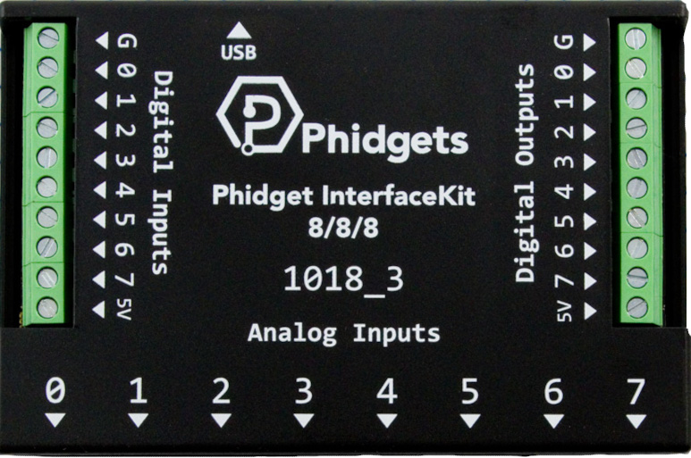
 Design with PhidgetInterfaceKit 8/8/8 in Cirkit Designer
Introduction
The PhidgetInterfaceKit 8/8/8 (Manufacturer Part ID: 1018_3) is a versatile interface board designed to connect a wide range of sensors and actuators. It features 8 digital inputs, 8 digital outputs, and 8 analog inputs, making it an excellent choice for robotics, automation, and data acquisition projects. This component is ideal for hobbyists, educators, and professionals who need a reliable and easy-to-use interface for their electronic systems.
Explore Projects Built with PhidgetInterfaceKit 8/8/8
 Open Project in Cirkit Designer
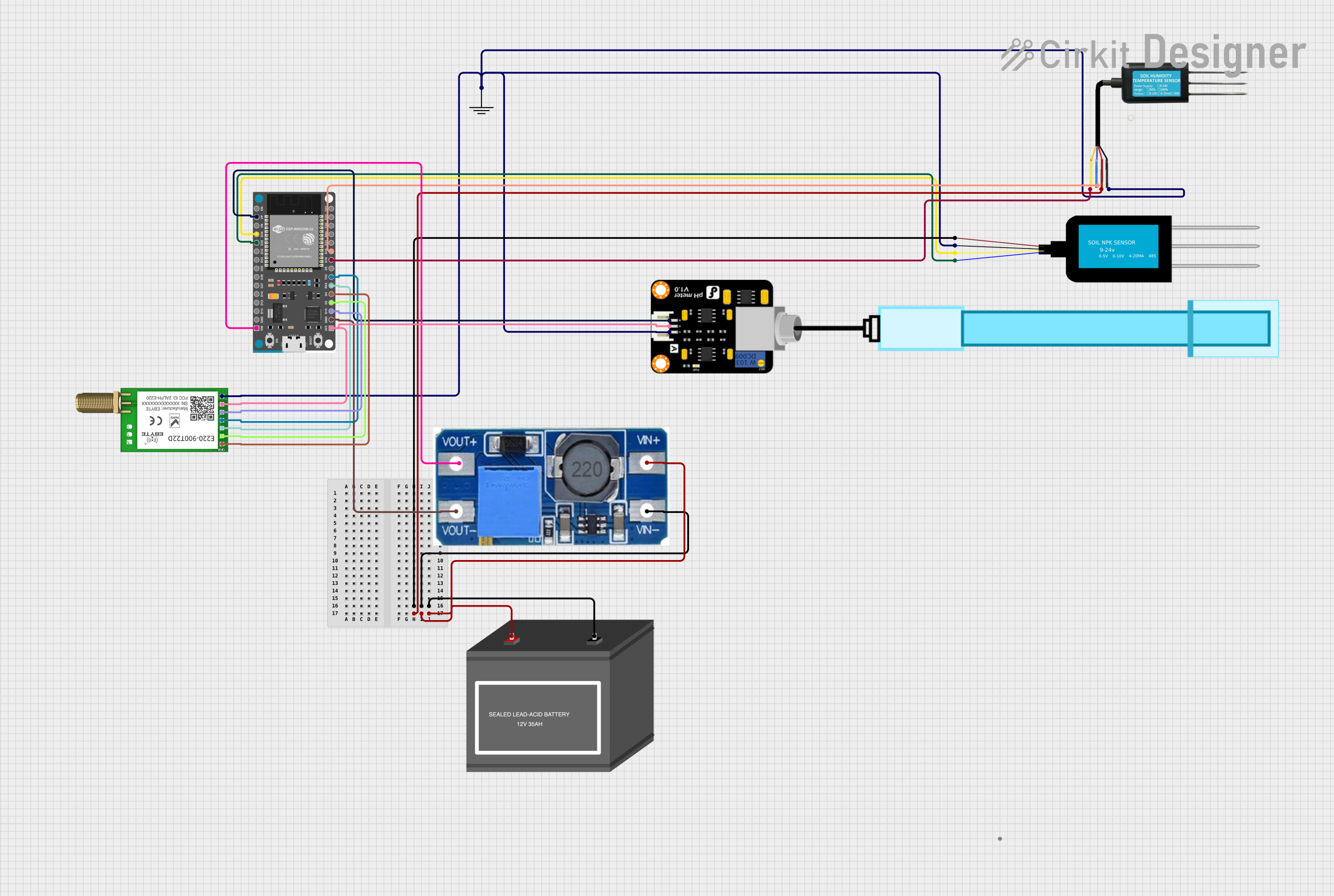 Open Project in Cirkit Designer
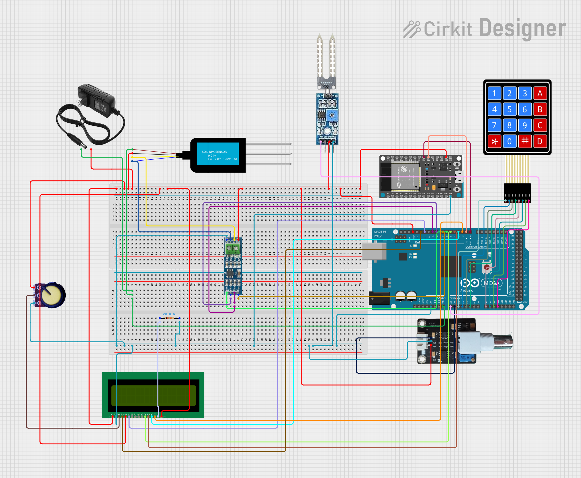 Open Project in Cirkit Designer
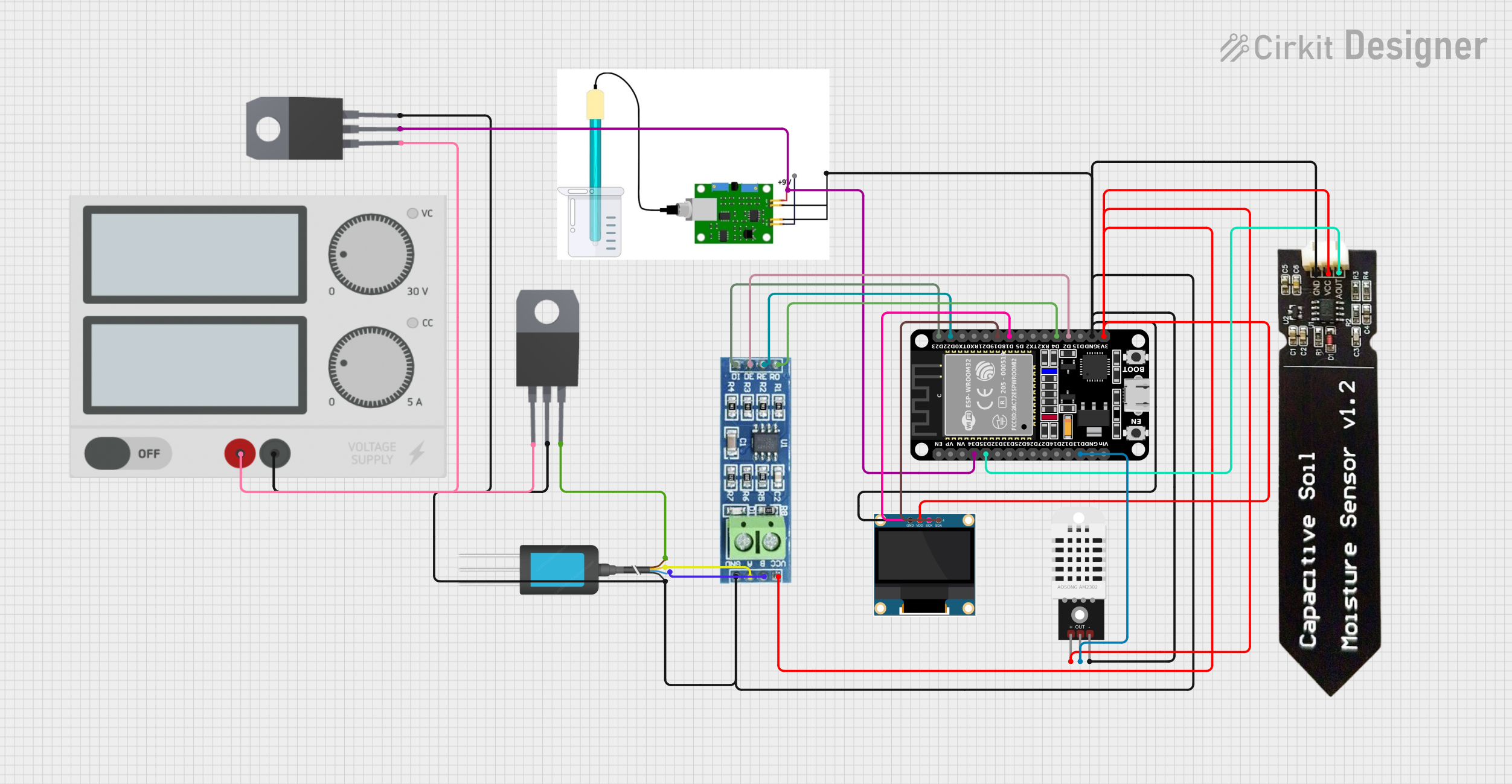 Open Project in Cirkit Designer
Explore Projects Built with PhidgetInterfaceKit 8/8/8
Open Project in Cirkit DesignerOpen Project in Cirkit DesignerOpen Project in Cirkit DesignerOpen Project in Cirkit DesignerCommon Applications
- Robotics and automation systems
- Environmental monitoring and data logging
- Home automation projects
- Prototyping and educational experiments
- Industrial control systems
Technical Specifications
Key Technical Details
| Parameter | Specification |
|---|---|
| Manufacturer | Phidget |
| Part ID | 1018_3 |
| Digital Inputs | 8 (5V logic, TTL-compatible) |
| Digital Outputs | 8 (Open collector, max 30V, 1A) |
| Analog Inputs | 8 (10-bit resolution, 0-5V range) |
| Communication Interface | USB 2.0 |
| Power Supply | USB-powered (5V) |
| Operating Temperature | 0°C to 70°C |
| Dimensions | 122mm x 78mm x 20mm |
Pin Configuration and Descriptions
Digital Inputs
| Pin Number | Description | Notes |
|---|---|---|
| 1-8 | Digital Input Channels (DI) | Accepts 5V logic signals |
| GND | Ground | Common ground for inputs |
Digital Outputs
| Pin Number | Description | Notes |
|---|---|---|
| 1-8 | Digital Output Channels (DO) | Open collector, max 30V, 1A |
| GND | Ground | Common ground for outputs |
Analog Inputs
| Pin Number | Description | Notes |
|---|---|---|
| 1-8 | Analog Input Channels (AI) | 10-bit resolution, 0-5V range |
| GND | Ground | Common ground for inputs |
USB Interface
| Pin Number | Description | Notes |
|---|---|---|
| USB | USB Type-B Connector | For power and data communication |
Usage Instructions
How to Use the Component in a Circuit
Connect Sensors and Actuators:
- Attach sensors to the analog input pins (AI1-AI8) for reading analog signals.
- Connect actuators (e.g., LEDs, relays) to the digital output pins (DO1-DO8).
- Use the digital input pins (DI1-DI8) for reading digital signals from switches or other devices.
Power the Board:
- Connect the PhidgetInterfaceKit to your computer or USB power source using a USB Type-B cable.
Install Drivers and Libraries:
- Download and install the Phidget drivers and libraries from the Phidget website.
- Ensure the drivers are properly installed before proceeding.
Write and Upload Code:
- Use the Phidget API to communicate with the board. The API supports multiple programming languages, including Python, C#, Java, and more.
Important Considerations and Best Practices
- Ensure that the connected sensors and actuators operate within the voltage and current limits of the board.
- Use external pull-up resistors for digital inputs if required by your application.
- Avoid exceeding the maximum current rating (1A) for digital outputs to prevent damage.
- Keep the board in a dry, dust-free environment to ensure reliable operation.
Example Code for Arduino UNO
Although the PhidgetInterfaceKit is typically used with a computer, it can also interface with an Arduino UNO via digital and analog pins. Below is an example of how to read an analog input and control a digital output:
// Example: Reading an analog input and controlling a digital output
const int analogInputPin = A0; // Connect AI1 to A0 on Arduino
const int digitalOutputPin = 2; // Connect DO1 to pin 2 on Arduino

void setup() {
  pinMode(digitalOutputPin, OUTPUT); // Set digital output pin as output
  Serial.begin(9600); // Initialize serial communication
}

void loop() {
  int sensorValue = analogRead(analogInputPin); // Read analog input
  Serial.print("Analog Input Value: ");
  Serial.println(sensorValue); // Print the value to the Serial Monitor

  if (sensorValue > 512) {
    digitalWrite(digitalOutputPin, HIGH); // Turn on digital output
  } else {
    digitalWrite(digitalOutputPin, LOW); // Turn off digital output
  }

  delay(100); // Small delay for stability
}
Troubleshooting and FAQs
Common Issues
The board is not detected by the computer:
- Ensure the USB cable is securely connected.
- Verify that the Phidget drivers are installed correctly.
- Try using a different USB port or cable.
Digital outputs are not working:
- Check if the connected load exceeds the maximum current rating (1A).
- Ensure the ground (GND) is properly connected.
Analog inputs are not reading correctly:
- Verify that the input voltage is within the 0-5V range.
- Check for loose or faulty connections.
Intermittent or unstable operation:
- Ensure the board is operating within the specified temperature range (0°C to 70°C).
- Avoid using the board in environments with excessive electrical noise.
Solutions and Tips for Troubleshooting
- Use the Phidget Control Panel software to test the board's functionality before writing custom code.
- Double-check all connections and ensure proper wiring.
- Refer to the official PhidgetInterfaceKit 8/8/8 User Guide for additional support and resources.
By following this documentation, you can effectively integrate the PhidgetInterfaceKit 8/8/8 into your projects and troubleshoot any issues that may arise.