How to Use DC-DC 12V-5V: Examples, Pinouts, and Specs
Introduction
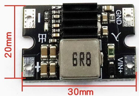
The DC-DC 12V-5V converter is a step-down voltage regulator designed to convert a 12V input voltage to a stable 5V output. This component is widely used in electronic circuits to power devices that require a lower voltage, such as microcontrollers, sensors, and USB-powered devices. Its compact size and high efficiency make it an essential component in automotive, industrial, and DIY electronics projects.
Explore Projects Built with DC-DC 12V-5V


Explore Projects Built with DC-DC 12V-5V
Common Applications and Use Cases
- Powering 5V microcontrollers (e.g., Arduino, Raspberry Pi)
- USB device charging (e.g., smartphones, tablets)
- Automotive electronics (e.g., powering GPS modules, dash cams)
- Battery-powered systems requiring voltage regulation
- DIY projects and prototyping
Technical Specifications
The following table outlines the key technical details of the DC-DC 12V-5V converter:
| Parameter | Value |
|---|---|
| Input Voltage Range | 8V to 24V |
| Output Voltage | 5V ± 0.1V |
| Maximum Output Current | 3A (typical), 5A (peak) |
| Efficiency | Up to 95% |
| Ripple Voltage | < 50mV |
| Operating Temperature | -40°C to +85°C |
| Dimensions | 25mm x 15mm x 10mm (approximate) |
Pin Configuration and Descriptions
The DC-DC 12V-5V converter typically has four pins or terminals. The table below describes each pin:
| Pin Name | Description |
|---|---|
| VIN | Input voltage pin (connect to 12V power source) |
| GND | Ground pin (common ground for input and output) |
| VOUT | Output voltage pin (provides regulated 5V output) |
| EN (optional) | Enable pin (used to turn the converter on/off) |
Note: Some models may not include an enable pin. Always refer to the specific datasheet for your module.
Usage Instructions
How to Use the Component in a Circuit
Connect the Input Voltage (VIN):
Attach the VIN pin to a 12V power source. Ensure the input voltage is within the specified range (8V to 24V) to avoid damaging the converter.Connect the Ground (GND):
Connect the GND pin to the ground of your circuit. This serves as the common reference point for both input and output.Connect the Output Voltage (VOUT):
Attach the VOUT pin to the device or circuit requiring a 5V power supply. Ensure the connected load does not exceed the maximum output current rating.Optional Enable Pin (EN):
If the module includes an enable pin, connect it to a logic HIGH (e.g., 3.3V or 5V) to activate the converter. Pulling it LOW or leaving it unconnected may disable the output.
Important Considerations and Best Practices
- Heat Dissipation: For high-current applications, ensure proper heat dissipation by using a heatsink or providing adequate ventilation.
- Input Voltage Filtering: Use a capacitor (e.g., 100µF) across the input terminals to reduce noise and improve stability.
- Output Voltage Filtering: Add a capacitor (e.g., 10µF) across the output terminals to minimize ripple voltage.
- Polarity Protection: Double-check the polarity of the input and output connections to prevent damage to the module.
- Load Testing: Before connecting sensitive devices, test the output voltage and current with a dummy load to ensure proper operation.
Example: Using with an Arduino UNO
The DC-DC 12V-5V converter can be used to power an Arduino UNO from a 12V source. Below is an example circuit and code:
Circuit Connections
- Connect the VIN pin of the converter to a 12V power source.
- Connect the GND pin of the converter to the ground of the power source and the Arduino.
- Connect the VOUT pin of the converter to the 5V pin of the Arduino UNO.
Example Code
// Example code to blink an LED using Arduino UNO powered by DC-DC 12V-5V converter
// Ensure the DC-DC converter is providing a stable 5V to the Arduino's 5V pin.

const int ledPin = 13; // Built-in LED pin on Arduino UNO

void setup() {
  pinMode(ledPin, OUTPUT); // Set LED pin as output
}

void loop() {
  digitalWrite(ledPin, HIGH); // Turn the LED on
  delay(1000);                // Wait for 1 second
  digitalWrite(ledPin, LOW);  // Turn the LED off
  delay(1000);                // Wait for 1 second
}
Warning: Do not connect the Arduino's VIN pin when using the 5V pin for power input.
Troubleshooting and FAQs
Common Issues and Solutions
No Output Voltage:
- Cause: Incorrect input voltage or loose connections.
- Solution: Verify the input voltage is within the specified range and check all connections.
Overheating:
- Cause: Excessive load current or poor ventilation.
- Solution: Reduce the load current or improve heat dissipation with a heatsink.
High Ripple Voltage:
- Cause: Insufficient filtering capacitors.
- Solution: Add capacitors across the input and output terminals as recommended.
Device Not Powering On:
- Cause: Enable pin not connected or set to LOW.
- Solution: Connect the enable pin to a logic HIGH or check the module's datasheet for default behavior.
FAQs
Q: Can I use this converter with a 24V input?
A: Yes, as long as the input voltage does not exceed 24V and the load current is within the specified limits.
Q: Is the output voltage adjustable?
A: Most DC-DC 12V-5V converters provide a fixed 5V output. For adjustable output, look for a model with a potentiometer.
Q: Can I use this converter to charge a USB device?
A: Yes, the 5V output is suitable for USB devices. Ensure the current rating meets the device's requirements.
Q: What happens if I reverse the input polarity?
A: Reversing the input polarity may damage the module. Use a diode for polarity protection if needed.