How to Use XL6019E1 DC-DC step-up/step-down: Examples, Pinouts, and Specs
Introduction
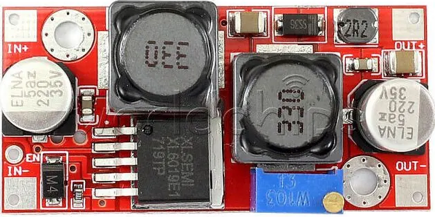
The XL6019E1 is a versatile DC-DC converter capable of both step-up (boost) and step-down (buck) voltage regulation. This flexibility makes it ideal for applications requiring stable voltage output across varying input conditions. It is widely used in power supply systems, battery-powered devices, LED drivers, and industrial control systems. Its high efficiency and wide input voltage range make it a reliable choice for both hobbyist and professional projects.
Explore Projects Built with XL6019E1 DC-DC step-up/step-down


Explore Projects Built with XL6019E1 DC-DC step-up/step-down
Common Applications
- Battery-powered devices requiring stable voltage output
- LED lighting systems
- Solar power systems
- Industrial control systems
- General-purpose power supply modules
Technical Specifications
The XL6019E1 is designed to handle a wide range of input and output voltages, making it suitable for diverse applications. Below are its key technical specifications:
| Parameter | Value |
|---|---|
| Input Voltage Range | 5V to 32V |
| Output Voltage Range | 1.25V to 35V |
| Output Current | Up to 5A (with proper heat dissipation) |
| Switching Frequency | 180 kHz |
| Efficiency | Up to 96% (depending on load conditions) |
| Operating Temperature | -40°C to +85°C |
| Package Type | TO-263-5L |
Pin Configuration and Descriptions
The XL6019E1 has a 5-pin configuration. Below is the pinout and description:
| Pin Number | Pin Name | Description |
|---|---|---|
| 1 | VIN | Input voltage pin (5V to 32V). Connect to power source. |
| 2 | GND | Ground pin. Connect to circuit ground. |
| 3 | SW | Switching pin. Connect to the inductor and diode. |
| 4 | FB | Feedback pin. Used to set the output voltage via a resistor divider. |
| 5 | EN | Enable pin. High to enable the module, low to disable. |
Usage Instructions
How to Use the XL6019E1 in a Circuit
- Input Voltage Connection: Connect the input voltage source (5V to 32V) to the
VINpin. Ensure the input voltage is within the specified range. - Output Voltage Adjustment: Use a resistor divider network connected to the
FBpin to set the desired output voltage. The formula for output voltage is: [ V_{OUT} = V_{REF} \times \left(1 + \frac{R1}{R2}\right) ] where ( V_{REF} ) is typically 1.25V. - Inductor and Diode Selection: Choose an appropriate inductor and Schottky diode based on the input/output voltage and current requirements. Refer to the datasheet for recommended values.
- Enable Pin: Connect the
ENpin to a high logic level (e.g., VIN) to enable the module. Pull it low to disable the module. - Heat Dissipation: For high-current applications, ensure proper heat dissipation using a heatsink or adequate PCB thermal design.
Example: Connecting XL6019E1 to an Arduino UNO
The XL6019E1 can be used to power an Arduino UNO by stepping down a higher voltage (e.g., 12V) to 5V. Below is an example circuit and Arduino code to monitor the output voltage.
Circuit Connections
- Connect a 12V power source to the
VINpin of the XL6019E1. - Set the output voltage to 5V using a resistor divider on the
FBpin. - Connect the
GNDpin of the XL6019E1 to the Arduino's GND. - Connect the output of the XL6019E1 to the Arduino's 5V pin.
Arduino Code
// This code reads the output voltage of the XL6019E1 using an analog pin
// and displays the value on the serial monitor.

const int voltagePin = A0; // Analog pin connected to the output voltage
const float referenceVoltage = 5.0; // Arduino reference voltage (5V)
const int adcResolution = 1024; // 10-bit ADC resolution

void setup() {
  Serial.begin(9600); // Initialize serial communication
  pinMode(voltagePin, INPUT); // Set the voltage pin as input
}

void loop() {
  int adcValue = analogRead(voltagePin); // Read the ADC value
  float outputVoltage = (adcValue * referenceVoltage) / adcResolution;

  // Print the output voltage to the serial monitor
  Serial.print("Output Voltage: ");
  Serial.print(outputVoltage);
  Serial.println(" V");

  delay(1000); // Wait for 1 second before the next reading
}
Important Considerations
- Input Voltage: Ensure the input voltage is always higher than the minimum required for proper operation.
- Output Current: Do not exceed the maximum output current of 5A. Use proper heat dissipation for high-current applications.
- Inductor Selection: Use an inductor with sufficient current rating to avoid saturation.
- Feedback Resistors: Use precision resistors for accurate output voltage regulation.
Troubleshooting and FAQs
Common Issues and Solutions
No Output Voltage
- Cause: The
ENpin is not connected or is pulled low. - Solution: Ensure the
ENpin is connected to a high logic level (e.g., VIN).
- Cause: The
Output Voltage is Incorrect
- Cause: Incorrect resistor values in the feedback network.
- Solution: Verify the resistor values and recalculate using the output voltage formula.
Overheating
- Cause: Excessive current draw or insufficient heat dissipation.
- Solution: Use a heatsink or improve PCB thermal design. Ensure the load current does not exceed 5A.
High Output Ripple
- Cause: Poor capacitor selection or layout issues.
- Solution: Use low-ESR capacitors and ensure proper PCB layout.
FAQs
Can the XL6019E1 be used for both step-up and step-down applications?
- Yes, the XL6019E1 is designed for both boost and buck voltage regulation.
What is the maximum efficiency of the XL6019E1?
- The XL6019E1 can achieve up to 96% efficiency, depending on the load and input/output conditions.
Can I use the XL6019E1 with a 3.3V microcontroller?
- Yes, but ensure the output voltage is set to 3.3V and the input voltage is within the specified range.
What type of diode should I use with the XL6019E1?
- Use a high-speed Schottky diode with a current rating equal to or greater than the load current.
By following this documentation, you can effectively integrate the XL6019E1 into your projects and troubleshoot common issues.