
How to Use SO18W: Examples, Pinouts, and Specs
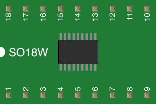
 Design with SO18W in Cirkit Designer
Introduction
The SO18W is a small outline integrated circuit (IC) package with 18 pins, manufactured by Generic. It is specifically designed for surface-mount technology (SMT) applications, offering a compact form factor and efficient thermal performance. This package is widely used in modern electronic devices where space-saving and reliability are critical.
Explore Projects Built with SO18W
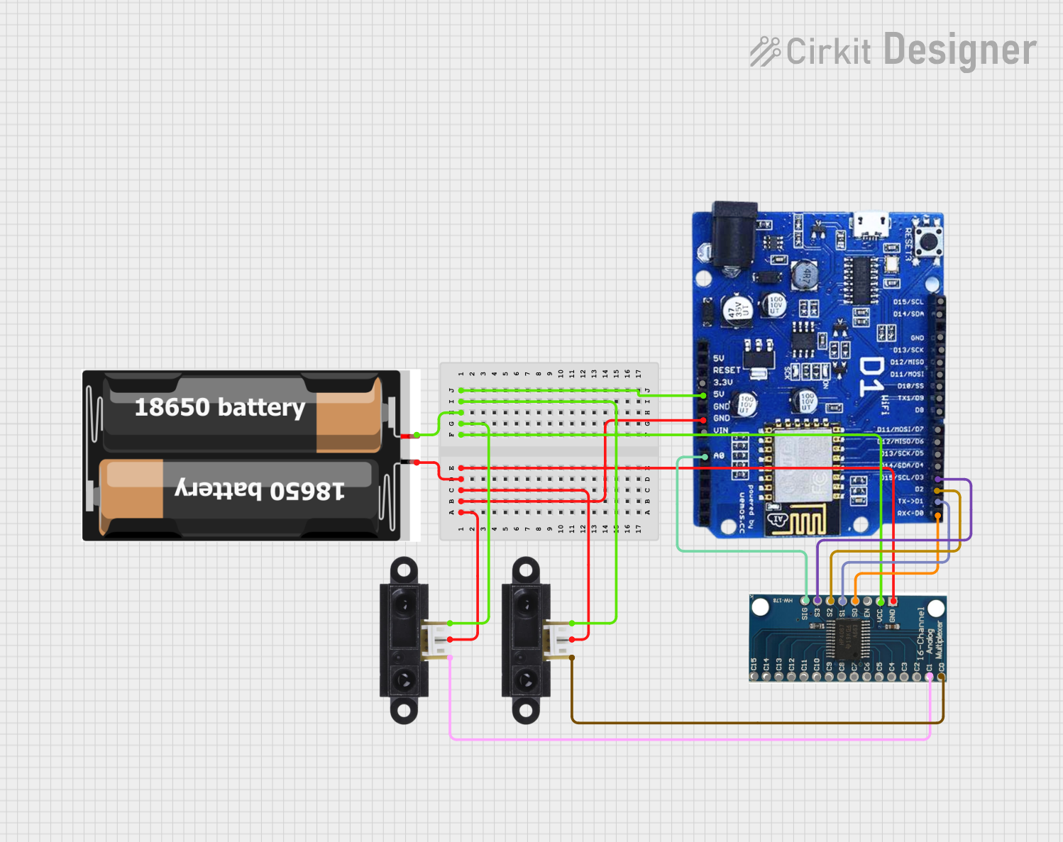 Open Project in Cirkit Designer
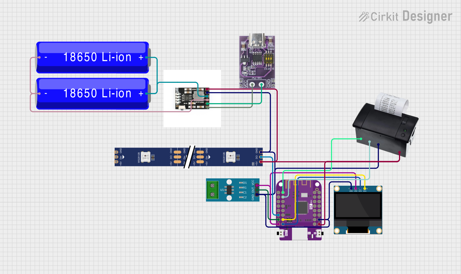 Open Project in Cirkit Designer
 Open Project in Cirkit Designer
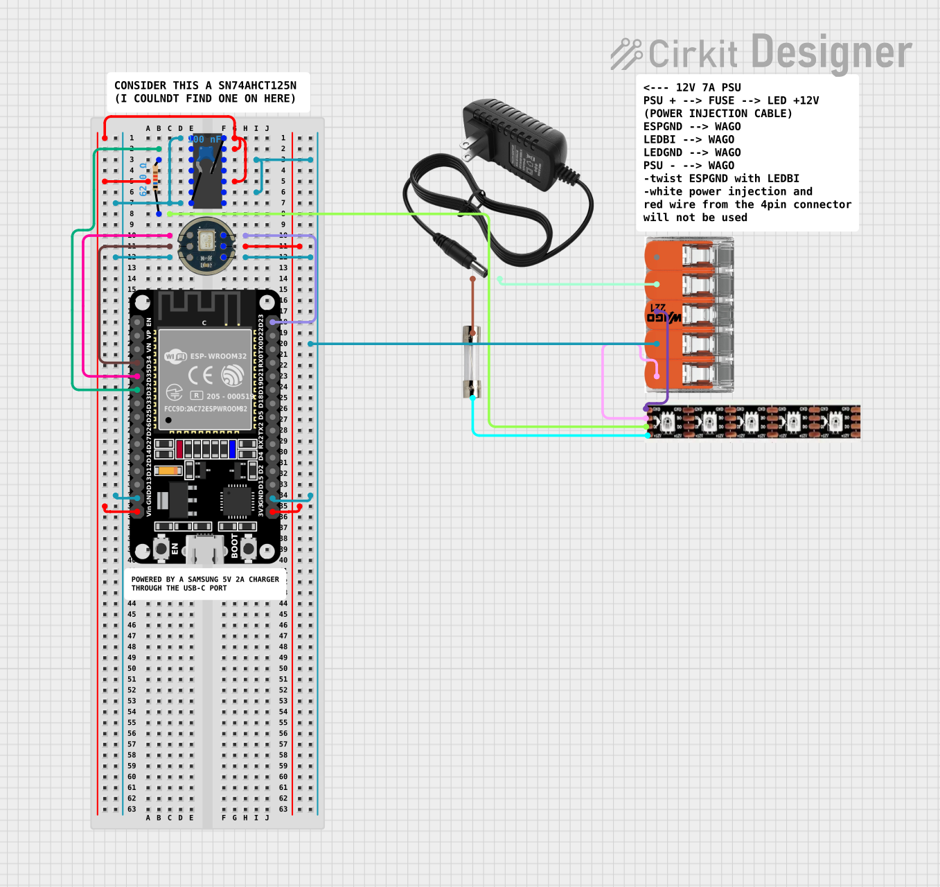 Open Project in Cirkit Designer
Explore Projects Built with SO18W
Open Project in Cirkit DesignerOpen Project in Cirkit DesignerOpen Project in Cirkit DesignerOpen Project in Cirkit DesignerCommon Applications and Use Cases
- Microcontrollers and digital signal processors (DSPs)
- Analog and digital ICs for consumer electronics
- Power management ICs
- Communication modules
- Automotive electronics
- Industrial control systems
Technical Specifications
Key Technical Details
| Parameter | Value |
|---|---|
| Manufacturer | Generic |
| Part ID | SO18W |
| Package Type | Small Outline (SO) |
| Number of Pins | 18 |
| Pin Pitch | 1.27 mm |
| Body Width | 7.5 mm |
| Body Length | 11.5 mm |
| Maximum Height | 2.65 mm |
| Thermal Resistance | Low (varies by IC design) |
| Mounting Type | Surface Mount Technology (SMT) |
| Operating Temperature | -40°C to +125°C |
| Moisture Sensitivity | Level 3 (JEDEC standard) |
Pin Configuration and Descriptions
The SO18W package has 18 pins, which are typically configured based on the specific IC housed within the package. Below is a general example of pin configuration for a typical IC:
| Pin Number | Pin Name | Description |
|---|---|---|
| 1 | VCC | Power supply input |
| 2 | GND | Ground |
| 3-8 | I/O1 - I/O6 | General-purpose input/output pins |
| 9 | RESET | Reset input |
| 10-15 | I/O7 - I/O12 | General-purpose input/output pins |
| 16 | CLK | Clock input |
| 17 | ENABLE | Enable signal input |
| 18 | NC (or VOUT) | No connection or output (varies by IC) |
Note: The actual pin configuration depends on the specific IC design within the SO18W package. Always refer to the datasheet of the IC for precise pin assignments.
Usage Instructions
How to Use the SO18W in a Circuit
- PCB Design: Ensure your PCB layout matches the SO18W footprint. The pin pitch is 1.27 mm, and the body dimensions are 7.5 mm x 11.5 mm.
- Soldering: Use reflow soldering for mounting the SO18W package. Ensure the solder paste is applied evenly to avoid bridging between pins.
- Power Supply: Verify the voltage and current requirements of the IC housed in the SO18W package. Connect the VCC and GND pins appropriately.
- Signal Connections: Connect the input/output pins to the corresponding signals in your circuit. Use decoupling capacitors near the power pins to reduce noise.
- Thermal Management: If the IC generates significant heat, ensure proper thermal dissipation through PCB design (e.g., thermal vias or copper planes).
Important Considerations and Best Practices
- Moisture Sensitivity: The SO18W package has a moisture sensitivity level of 3. Store it in a dry environment and bake it before soldering if necessary.
- ESD Protection: Handle the package with care to avoid electrostatic discharge (ESD) damage.
- Pin Alignment: Double-check the orientation of the package before soldering to avoid incorrect connections.
- Testing: After soldering, test the circuit for continuity and functionality to ensure proper operation.
Example: Connecting SO18W to an Arduino UNO
If the IC in the SO18W package is a digital sensor or communication module, you can connect it to an Arduino UNO. Below is an example code snippet for interfacing with a hypothetical I2C device in the SO18W package:
#include <Wire.h> // Include the Wire library for I2C communication

#define DEVICE_ADDRESS 0x40 // Replace with the actual I2C address of the device

void setup() {
  Wire.begin(); // Initialize I2C communication
  Serial.begin(9600); // Start serial communication for debugging

  // Send initialization command to the device
  Wire.beginTransmission(DEVICE_ADDRESS);
  Wire.write(0x01); // Example command to initialize the device
  Wire.endTransmission();

  Serial.println("Device initialized.");
}

void loop() {
  Wire.beginTransmission(DEVICE_ADDRESS);
  Wire.write(0x02); // Example command to request data
  Wire.endTransmission();

  Wire.requestFrom(DEVICE_ADDRESS, 2); // Request 2 bytes of data
  if (Wire.available() == 2) {
    int data = Wire.read() << 8 | Wire.read(); // Combine two bytes into an integer
    Serial.print("Received data: ");
    Serial.println(data);
  }

  delay(1000); // Wait for 1 second before the next request
}
Note: Replace
DEVICE_ADDRESSand commands with the actual values specified in the IC datasheet.
Troubleshooting and FAQs
Common Issues Users Might Face
Bridged Pins During Soldering:
- Cause: Excess solder paste or improper alignment.
- Solution: Use a solder wick or desoldering pump to remove excess solder. Ensure proper alignment before reflow.
Device Not Responding:
- Cause: Incorrect power supply or signal connections.
- Solution: Verify the VCC, GND, and signal connections. Check for continuity with a multimeter.
Overheating:
- Cause: Insufficient thermal dissipation.
- Solution: Improve PCB thermal design with copper planes or heat sinks.
Moisture Damage:
- Cause: Exposure to high humidity before soldering.
- Solution: Bake the package at the recommended temperature before soldering.
FAQs
Q1: Can the SO18W package be hand-soldered?
A1: Yes, but it requires precision and a fine-tipped soldering iron. Reflow soldering is recommended for best results.
Q2: What is the maximum operating temperature of the SO18W package?
A2: The SO18W package can operate within a temperature range of -40°C to +125°C.
Q3: How do I identify pin 1 on the SO18W package?
A3: Pin 1 is typically marked with a dot or a chamfered edge on the package. Refer to the IC datasheet for details.
Q4: Is the SO18W package suitable for high-frequency applications?
A4: Yes, the SO18W package is commonly used for high-frequency ICs, but proper PCB design is crucial to minimize signal interference.
Q5: Can I use the SO18W package for prototyping?
A5: Yes, but you may need an SO18W-to-DIP adapter for breadboard compatibility.