How to Use Conector Anderson 2: Examples, Pinouts, and Specs
Introduction
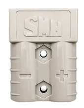
The Anderson Connector 2 is a high-current, genderless connector designed for quick, secure, and reliable electrical connections. It is widely used in applications requiring robust power delivery, such as battery packs, solar power systems, electric vehicles, and industrial equipment. Its modular design and durable construction make it a popular choice for both hobbyists and professionals.
Explore Projects Built with Conector Anderson 2


Explore Projects Built with Conector Anderson 2
Common Applications
- Battery connections for electric vehicles and robotics
- Solar panel and renewable energy systems
- High-current DC power distribution
- Industrial machinery and equipment
- RC (Radio-Controlled) vehicles and drones
Technical Specifications
Key Technical Details
| Parameter | Value |
|---|---|
| Maximum Voltage | 600V DC |
| Maximum Current | 30A, 50A, or 120A (depending on model) |
| Contact Material | Copper with silver plating |
| Housing Material | Polycarbonate (PC) |
| Operating Temperature | -20°C to +105°C |
| Connection Type | Genderless, snap-in design |
| Wire Gauge Compatibility | 10 AWG to 2 AWG (depending on model) |
Pin Configuration and Descriptions
The Anderson Connector 2 is a genderless connector, meaning both sides of the connector are identical. It uses two main pins for power connections. Below is a description of the pin layout:
| Pin Number | Description | Notes |
|---|---|---|
| 1 | Positive Terminal | Connects to the positive power line |
| 2 | Negative Terminal | Connects to the negative power line |
Usage Instructions
How to Use the Anderson Connector 2 in a Circuit
- Prepare the Wires: Strip the insulation from the wires to expose the appropriate length of conductor. Ensure the wire gauge matches the connector's specifications.
- Crimp the Contacts: Use a compatible crimping tool to securely attach the connector's contacts to the stripped wire ends. Ensure a firm and reliable crimp to avoid loose connections.
- Insert Contacts into Housing: Push the crimped contacts into the connector housing until they snap into place. The contacts are keyed to prevent incorrect insertion.
- Connect the Mating Connectors: Align the connectors and push them together until they click. The genderless design ensures a secure and reversible connection.
- Test the Connection: Verify the connection by checking for continuity and ensuring the connector is securely locked.
Important Considerations and Best Practices
- Wire Gauge: Always use wires that match the connector's rated wire gauge to ensure safe and efficient power transfer.
- Crimping Tool: Use a high-quality crimping tool designed for Anderson connectors to achieve a reliable connection.
- Polarity: Double-check the polarity of the connections to avoid damage to the circuit or connected devices.
- Environmental Protection: If used in outdoor or harsh environments, consider using additional protective measures, such as weatherproof housings or covers.
- Current Rating: Ensure the connector's current rating matches or exceeds the requirements of your application to prevent overheating or failure.
Example: Connecting to an Arduino UNO
While the Anderson Connector 2 is not directly used with low-power devices like the Arduino UNO, it can be part of a power distribution system supplying power to the Arduino. Below is an example of how to use the connector in a 12V power supply system for an Arduino:
// Example: Using a 12V power supply with Anderson Connector 2
// Ensure the 12V power supply is regulated and connected to the Arduino's VIN pin.

void setup() {
  // Initialize the Arduino
  Serial.begin(9600);
  Serial.println("Arduino powered via Anderson Connector 2.");
}

void loop() {
  // Main loop
  Serial.println("System running...");
  delay(1000); // Wait for 1 second
}
Troubleshooting and FAQs
Common Issues and Solutions
| Issue | Possible Cause | Solution |
|---|---|---|
| Loose connection | Improper crimping or insertion | Re-crimp the contacts and ensure they snap into place. |
| Overheating during operation | Exceeding current rating or poor contact | Verify current rating and check for secure connections. |
| Difficulty in mating connectors | Misalignment or debris in housing | Clean the connectors and align them properly before connecting. |
| Connector won't lock | Worn or damaged housing | Inspect the housing and replace if necessary. |
FAQs
Can the Anderson Connector 2 handle AC power?
Yes, it can handle AC power, but it is primarily designed for DC applications.Are the connectors waterproof?
The standard Anderson Connector 2 is not waterproof. For outdoor use, additional weatherproofing is recommended.Can I use soldering instead of crimping?
Crimping is the preferred method for Anderson connectors as it provides a more reliable and durable connection. Soldering is not recommended as it may weaken the connection under high current.What is the lifespan of the connector?
The Anderson Connector 2 is rated for thousands of mating cycles, depending on usage and environmental conditions.
By following this documentation, you can effectively use the Anderson Connector 2 in your projects and ensure reliable power connections.