Cirkit Designer Logo
Cirkit Designer
Your all-in-one circuit design IDE
Home / 
Component Documentation

How to Use PowerBoost 1000 Basic Pad USB: Examples, Pinouts, and Specs

Image of PowerBoost 1000 Basic Pad USB
Cirkit Designer LogoDesign with PowerBoost 1000 Basic Pad USB in Cirkit Designer

Introduction

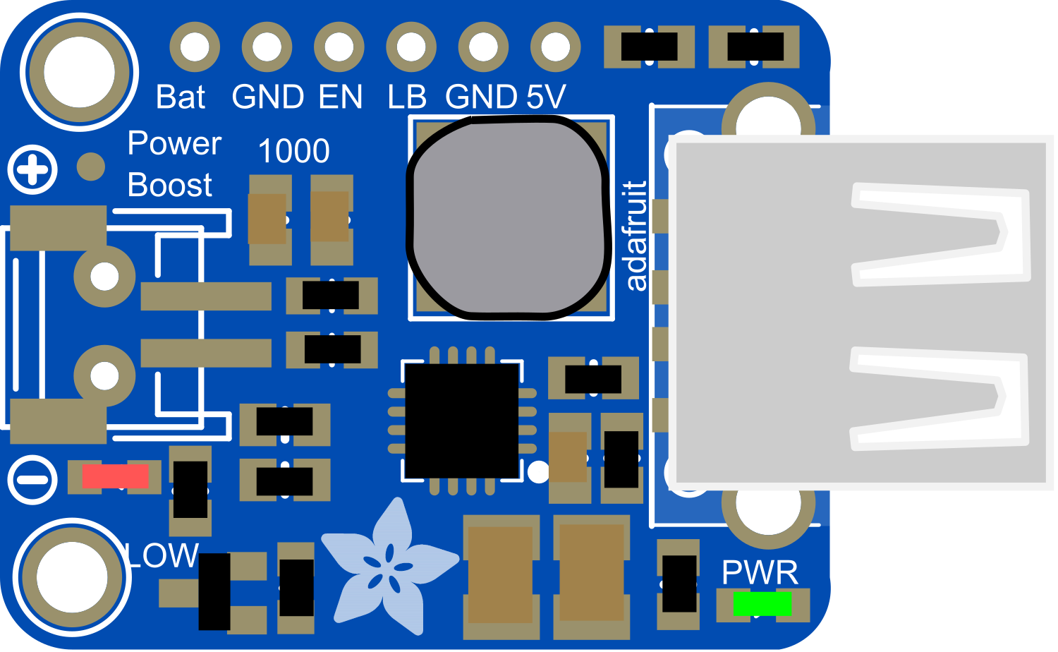
The PowerBoost 1000 Basic Pad USB is a versatile electronic component that integrates a power boost converter with a USB charging circuit. This module is designed to step up lower voltages to a stable 5V output, capable of delivering up to 1A of current, making it ideal for powering USB devices. It is commonly used in portable electronics, DIY power banks, and projects requiring a 5V USB power supply.

Explore Projects Built with PowerBoost 1000 Basic Pad USB

Use Cirkit Designer to design, explore, and prototype these projects online. Some projects support real-time simulation. Click "Open Project" to start designing instantly!
Battery-Powered Piezo Sensor Array with PowerBoost and Bridge Rectifier
Image of Copy of PIEZOELECTRIC : A project utilizing PowerBoost 1000 Basic Pad USB in a practical application
This circuit uses multiple piezo sensors connected to bridge rectifiers to convert AC signals from the sensors into DC. The rectified DC is then used to charge a 18650 Li-ion battery, which powers a PowerBoost 1000 Basic module to provide a stable 5V output.
Cirkit Designer LogoOpen Project in Cirkit Designer
Arduino Mega 2560 Based Security System with Fingerprint Authentication and SMS Alerts
Image of Door security system: A project utilizing PowerBoost 1000 Basic Pad USB in a practical application
This circuit features an Arduino Mega 2560 microcontroller interfaced with a SIM800L GSM module, two fingerprint scanners, an I2C LCD display, an IR sensor, and a piezo buzzer. Power management is handled by a PowerBoost 1000 Basic Pad USB, a TP4056 charging module, and a Li-ion 18650 battery, with an option to use a Mini AC-DC 110V-230V to 5V 700mA module for direct power supply. The primary functionality appears to be a security system with GSM communication capabilities, biometric access control, and visual/audible feedback.
Cirkit Designer LogoOpen Project in Cirkit Designer
Dual-Microcontroller Audio Processing System with Visual Indicators and Battery Management
Image of proto thesis 2: A project utilizing PowerBoost 1000 Basic Pad USB in a practical application
This is a portable audio-visual device featuring two Wemos microcontrollers for processing, Adafruit MAX4466 microphone amplifiers for audio input, and an LCD TFT screen for display. It includes power management with TP4056 modules and LiPo batteries, and user-controlled toggle and rocker switches.
Cirkit Designer LogoOpen Project in Cirkit Designer
Battery-Powered Raspberry Pi Zero with OLED Display and EmStat Pico for Portable Data Acquisition
Image of RPI Zero Prototype: A project utilizing PowerBoost 1000 Basic Pad USB in a practical application
This circuit is a portable system powered by a 3.7V LiPo battery, which is boosted to 5V using an Adafruit PowerBoost 1000C to power a Raspberry Pi Zero and an EmStat Pico. The Raspberry Pi Zero interfaces with an OLED display via I2C and a tactile switch for user input, while the EmStat Pico communicates with the Raspberry Pi over UART for data acquisition or control purposes.
Cirkit Designer LogoOpen Project in Cirkit Designer

Explore Projects Built with PowerBoost 1000 Basic Pad USB

Use Cirkit Designer to design, explore, and prototype these projects online. Some projects support real-time simulation. Click "Open Project" to start designing instantly!
Image of Copy of PIEZOELECTRIC : A project utilizing PowerBoost 1000 Basic Pad USB in a practical application
Battery-Powered Piezo Sensor Array with PowerBoost and Bridge Rectifier
This circuit uses multiple piezo sensors connected to bridge rectifiers to convert AC signals from the sensors into DC. The rectified DC is then used to charge a 18650 Li-ion battery, which powers a PowerBoost 1000 Basic module to provide a stable 5V output.
Cirkit Designer LogoOpen Project in Cirkit Designer
Image of Door security system: A project utilizing PowerBoost 1000 Basic Pad USB in a practical application
Arduino Mega 2560 Based Security System with Fingerprint Authentication and SMS Alerts
This circuit features an Arduino Mega 2560 microcontroller interfaced with a SIM800L GSM module, two fingerprint scanners, an I2C LCD display, an IR sensor, and a piezo buzzer. Power management is handled by a PowerBoost 1000 Basic Pad USB, a TP4056 charging module, and a Li-ion 18650 battery, with an option to use a Mini AC-DC 110V-230V to 5V 700mA module for direct power supply. The primary functionality appears to be a security system with GSM communication capabilities, biometric access control, and visual/audible feedback.
Cirkit Designer LogoOpen Project in Cirkit Designer
Image of proto thesis 2: A project utilizing PowerBoost 1000 Basic Pad USB in a practical application
Dual-Microcontroller Audio Processing System with Visual Indicators and Battery Management
This is a portable audio-visual device featuring two Wemos microcontrollers for processing, Adafruit MAX4466 microphone amplifiers for audio input, and an LCD TFT screen for display. It includes power management with TP4056 modules and LiPo batteries, and user-controlled toggle and rocker switches.
Cirkit Designer LogoOpen Project in Cirkit Designer
Image of RPI Zero Prototype: A project utilizing PowerBoost 1000 Basic Pad USB in a practical application
Battery-Powered Raspberry Pi Zero with OLED Display and EmStat Pico for Portable Data Acquisition
This circuit is a portable system powered by a 3.7V LiPo battery, which is boosted to 5V using an Adafruit PowerBoost 1000C to power a Raspberry Pi Zero and an EmStat Pico. The Raspberry Pi Zero interfaces with an OLED display via I2C and a tactile switch for user input, while the EmStat Pico communicates with the Raspberry Pi over UART for data acquisition or control purposes.
Cirkit Designer LogoOpen Project in Cirkit Designer

Common Applications and Use Cases

  • Portable USB chargers
  • Battery-powered electronics
  • DIY electronics projects
  • Wearable devices
  • Raspberry Pi power supply

Technical Specifications

Key Technical Details

  • Input Voltage: 1.8V to 5.5V
  • Output Voltage: 5V regulated
  • Output Current: Up to 1A
  • Efficiency: 90% typical at full load
  • Quiescent Current: <5mA

Pin Configuration and Descriptions

Pin Name Description
VIN Input voltage (1.8V to 5.5V)
GND Ground connection
5V Regulated 5V output
EN Enable pin (active high)
BAT Battery connection for charging

Usage Instructions

How to Use the Component in a Circuit

  1. Connect the VIN pin to your unregulated input voltage source (1.8V to 5.5V).
  2. Attach the GND pin to the common ground in your circuit.
  3. The 5V pin will provide a regulated 5V output when the module is enabled.
  4. The EN pin can be left unconnected for always-on operation or connected to a logic high signal to enable the output.
  5. If using the USB charging functionality, connect a rechargeable battery to the BAT pin.

Important Considerations and Best Practices

  • Ensure the input voltage does not exceed 5.5V to prevent damage.
  • Do not draw more than 1A from the 5V output to maintain stable operation.
  • If the device becomes hot to the touch, reduce the load to prevent overheating.
  • For battery charging, use batteries compatible with the charging circuit specifications.

Troubleshooting and FAQs

Common Issues

  • Output voltage is unstable or too low: Check if the input voltage is within the specified range and the load does not exceed 1A.
  • The device is overheating: Ensure adequate ventilation and check if the load is too high.
  • No output voltage: Verify that the EN pin is receiving a high signal if used, and check all connections for proper soldering and contact.

Solutions and Tips for Troubleshooting

  • Double-check wiring and solder joints for any shorts or cold solder joints.
  • Measure the input voltage to ensure it falls within the specified range.
  • If using the EN pin, ensure it is receiving a logic high signal (above 2V).
  • For persistent issues, consult the manufacturer's datasheet and support forums.

FAQs

Q: Can I use the PowerBoost 1000 Basic Pad USB to charge my phone? A: Yes, as long as your phone charges via USB and requires 5V and no more than 1A.

Q: Is it possible to use solar panels as an input source? A: Yes, if the solar panel's output is within the 1.8V to 5.5V range.

Q: Can I connect multiple devices to the 5V output? A: You can connect multiple devices as long as the total current draw does not exceed 1A.

Q: How do I know if the battery is charging? A: The PowerBoost 1000 Basic does not have a charge status indicator. You would need additional circuitry to monitor the charging status.

Example Code for Arduino UNO

The following example demonstrates how to control the PowerBoost 1000 Basic Pad USB's enable pin using an Arduino UNO.

// Define the pin connected to the PowerBoost EN pin
const int enablePin = 7;

void setup() {
  // Set the enable pin as an output
  pinMode(enablePin, OUTPUT);
  
  // Start with the PowerBoost disabled
  digitalWrite(enablePin, LOW);
}

void loop() {
  // Enable the PowerBoost for 5 seconds
  digitalWrite(enablePin, HIGH);
  delay(5000);
  
  // Disable the PowerBoost for 5 seconds
  digitalWrite(enablePin, LOW);
  delay(5000);
}

Note: This code is a simple example to illustrate control of the PowerBoost 1000 Basic Pad USB. In a real-world application, you would need to consider the power requirements and behavior of the connected devices.