How to Use Terminal Block Breakout Board Module for Teensy 4.1, DIN Rail Mount Version: Examples, Pinouts, and Specs
Introduction
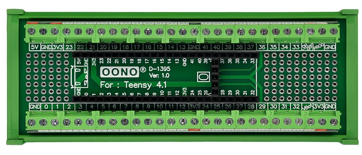
The Terminal Block Breakout Board Module for Teensy 4.1, DIN Rail Mount Version by CZH-LABS is a robust and versatile accessory designed to simplify connections to the Teensy 4.1 microcontroller. This breakout board provides a convenient way to access all the pins of the Teensy 4.1 via terminal blocks, making it ideal for industrial, prototyping, and educational applications. The DIN rail mount design ensures secure installation in control panels or enclosures.
Explore Projects Built with Terminal Block Breakout Board Module for Teensy 4.1, DIN Rail Mount Version

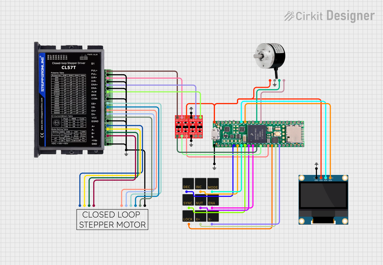
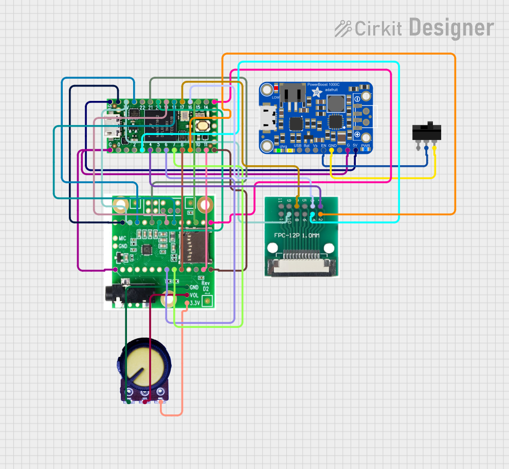

Explore Projects Built with Terminal Block Breakout Board Module for Teensy 4.1, DIN Rail Mount Version
Common Applications and Use Cases
- Industrial automation and control systems
- Rapid prototyping and testing of Teensy 4.1-based projects
- Educational setups for learning microcontroller programming
- Secure and organized wiring in enclosures or control panels
Technical Specifications
Key Technical Details
- Manufacturer: CZH-LABS
- Part ID: Terminal Block Breakout Board Module for Teensy 4.1, DIN Rail Mount Version
- Compatibility: Designed specifically for Teensy 4.1
- Mounting: DIN rail mountable
- Terminal Blocks: Screw-type terminal blocks for secure wire connections
- Operating Voltage: Supports Teensy 4.1's operating voltage (3.3V logic)
- Dimensions: Matches the Teensy 4.1 footprint with additional space for terminal blocks
- Material: High-quality PCB with durable terminal blocks and mounting hardware
Pin Configuration and Descriptions
The breakout board provides access to all Teensy 4.1 pins via terminal blocks. Below is the pin mapping:
| Terminal Block Pin | Teensy 4.1 Pin | Description |
|---|---|---|
| 1 | VIN | Input voltage (external power) |
| 2 | GND | Ground |
| 3 | 3.3V | 3.3V output |
| 4-33 | Digital Pins 0-29 | General-purpose I/O pins |
| 34-41 | Analog Pins A0-A7 | Analog input pins |
| 42 | USB Host Power | USB host power output |
| 43 | USB Host GND | USB host ground |
| 44-45 | I2C SDA, SCL | I2C communication pins |
| 46-47 | SPI MOSI, MISO | SPI communication pins |
| 48 | SPI SCK | SPI clock pin |
| 49-50 | CAN RX, TX | CAN bus communication pins |
Note: Ensure proper wiring to avoid short circuits or damage to the Teensy 4.1.
Usage Instructions
How to Use the Component in a Circuit
- Mounting the Breakout Board: Secure the breakout board to a DIN rail using the provided mounting hardware.
- Installing the Teensy 4.1: Insert the Teensy 4.1 into the breakout board's socket, ensuring proper alignment of pins.
- Connecting Wires: Use the screw-type terminal blocks to connect wires to the desired pins. Tighten the screws to secure the connections.
- Powering the Board: Provide power to the Teensy 4.1 via the VIN and GND terminal blocks or through the USB port.
- Programming the Teensy 4.1: Connect the Teensy 4.1 to a computer via USB and upload your program using the Arduino IDE or Teensy Loader.
Important Considerations and Best Practices
- Check Connections: Double-check all connections to ensure they match the intended pin configuration.
- Avoid Overloading: Do not exceed the Teensy 4.1's current and voltage ratings.
- Secure Wiring: Ensure all wires are securely fastened in the terminal blocks to prevent accidental disconnections.
- Use Proper Tools: Use a small screwdriver to tighten the terminal block screws without over-tightening.
Example Code for Arduino UNO-Compatible Setup
The following example demonstrates how to use the breakout board with a Teensy 4.1 to blink an LED connected to a digital pin:
// Example: Blink an LED connected to Digital Pin 13 on Teensy 4.1
// Ensure the LED's anode is connected to Pin 13 and cathode to GND.

#define LED_PIN 13  // Define the pin connected to the LED

void setup() {
  pinMode(LED_PIN, OUTPUT);  // Set the LED pin as an output
}

void loop() {
  digitalWrite(LED_PIN, HIGH);  // Turn the LED on
  delay(1000);                  // Wait for 1 second
  digitalWrite(LED_PIN, LOW);   // Turn the LED off
  delay(1000);                  // Wait for 1 second
}
Tip: Use jumper wires to connect the LED to the terminal block pins for easy prototyping.
Troubleshooting and FAQs
Common Issues Users Might Face
Teensy 4.1 Not Powering On
- Cause: Incorrect power supply or loose connections.
- Solution: Verify the power source and ensure the VIN and GND connections are secure.
No Response from Connected Devices
- Cause: Incorrect wiring or pin configuration.
- Solution: Double-check the wiring and ensure the correct pins are used for communication.
Loose Connections in Terminal Blocks
- Cause: Insufficient tightening of screws.
- Solution: Use a screwdriver to securely fasten the wires in the terminal blocks.
Interference or Noise in Signals
- Cause: Long wires or improper grounding.
- Solution: Use shorter wires and ensure proper grounding of the breakout board.
Solutions and Tips for Troubleshooting
- Inspect the Teensy 4.1: Ensure the microcontroller is properly seated in the breakout board socket.
- Test Individual Components: Isolate and test individual components to identify the source of the issue.
- Use a Multimeter: Check for continuity and proper voltage levels at the terminal block connections.
- Refer to Documentation: Consult the Teensy 4.1 and breakout board datasheets for additional guidance.
By following this documentation, users can effectively utilize the Terminal Block Breakout Board Module for Teensy 4.1, DIN Rail Mount Version in their projects, ensuring reliable and organized connections.