How to Use TIP32CPNP RESISTOR: Examples, Pinouts, and Specs
Introduction
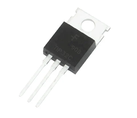
The TIP32C is a PNP power transistor manufactured by Arduino, designed for medium-power switching and amplification applications. It is part of the TIP series of transistors and is widely used in circuits requiring high current and voltage handling capabilities. The TIP32C is particularly suitable for audio amplifiers, motor drivers, and power regulation circuits.
This transistor is commonly used in applications where a PNP transistor is required to control high-current loads, such as motors, relays, or LEDs, in conjunction with microcontrollers like the Arduino UNO.
Explore Projects Built with TIP32CPNP RESISTOR
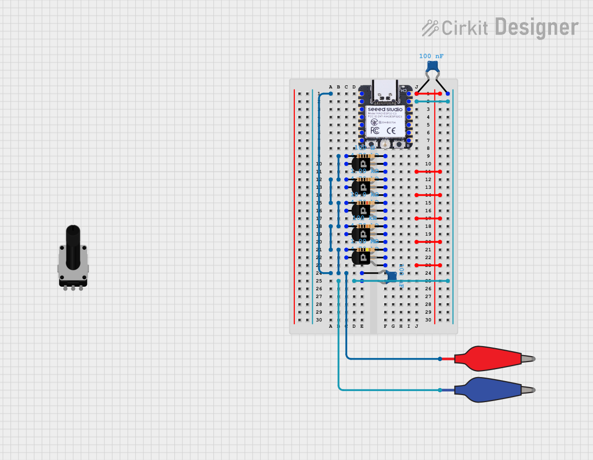

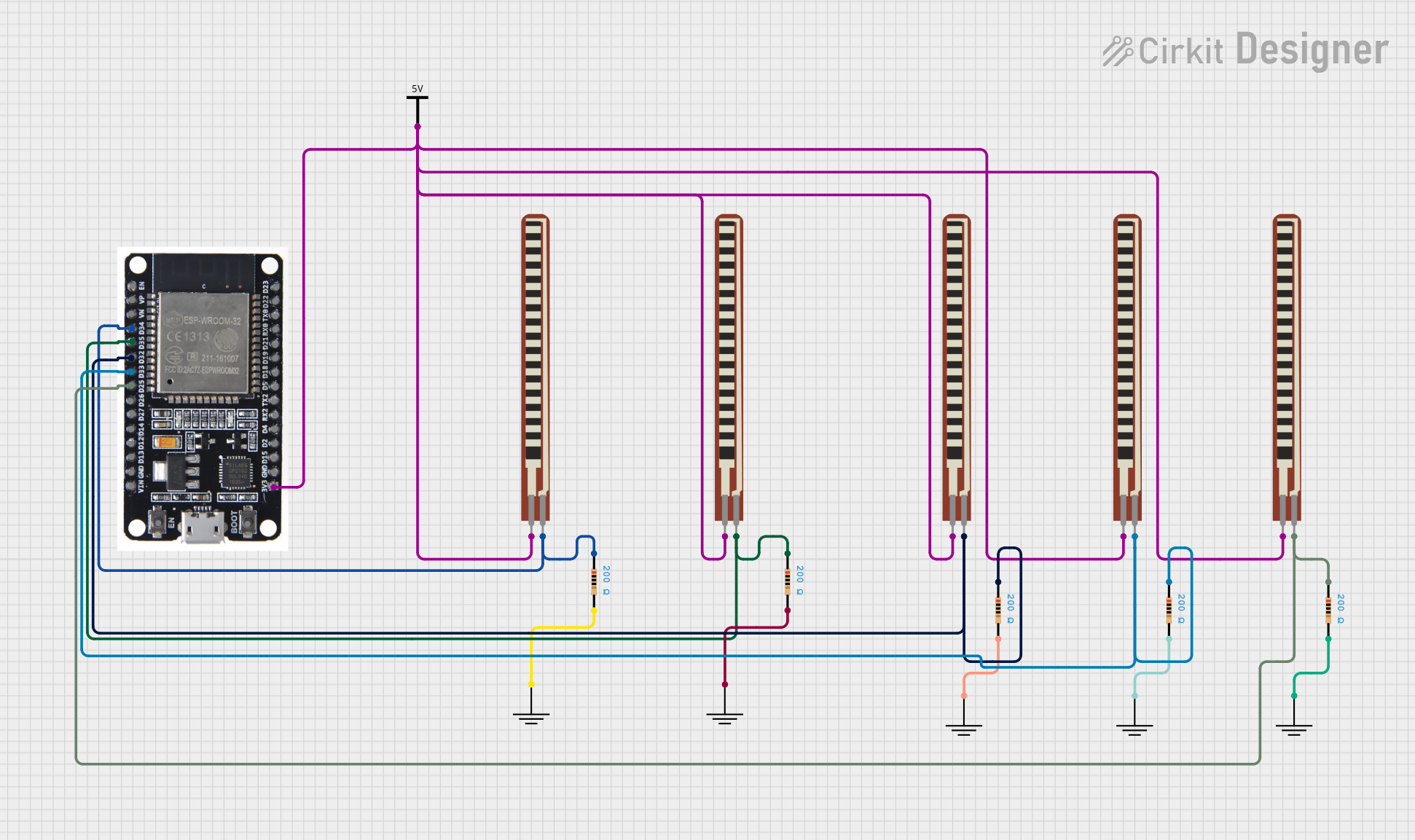
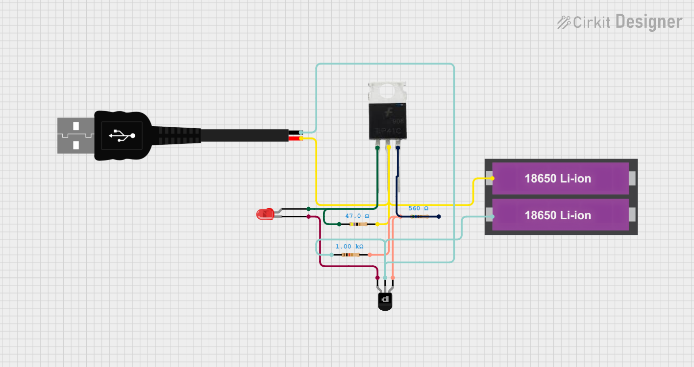
Explore Projects Built with TIP32CPNP RESISTOR
Technical Specifications
The TIP32C is a silicon PNP transistor with the following key specifications:
| Parameter | Value |
|---|---|
| Maximum Collector-Emitter Voltage (VCEO) | -100V |
| Maximum Collector-Base Voltage (VCBO) | -100V |
| Maximum Emitter-Base Voltage (VEBO) | -5V |
| Maximum Collector Current (IC) | -3A |
| Maximum Power Dissipation (PD) | 40W |
| DC Current Gain (hFE) | 15 to 75 |
| Operating Junction Temperature (TJ) | -65°C to +150°C |
| Package Type | TO-220 |
Pin Configuration
The TIP32C transistor comes in a TO-220 package with three pins. The pinout is as follows:
| Pin Number | Pin Name | Description |
|---|---|---|
| 1 | Base (B) | Controls the transistor's operation |
| 2 | Collector (C) | Current flows into this pin |
| 3 | Emitter (E) | Current flows out of this pin |
Usage Instructions
How to Use the TIP32C in a Circuit
Biasing the Transistor:
To use the TIP32C as a switch, connect the base pin to a control signal (e.g., from an Arduino UNO) through a current-limiting resistor. The resistor value can be calculated using Ohm's law to ensure the base current is sufficient to saturate the transistor.Connecting the Load:
- Connect the load (e.g., motor, LED, or relay) between the collector pin and the positive voltage supply.
- The emitter pin should be connected to the ground.
Driving with an Arduino UNO:
The TIP32C can be controlled directly by an Arduino UNO's digital output pin. Ensure the base resistor is appropriately sized to limit the current from the Arduino pin.
Example Circuit
Below is an example of using the TIP32C to control a 12V DC motor with an Arduino UNO:
Circuit Connections:
- Base (B): Connect to Arduino digital pin (e.g., D9) through a 1kΩ resistor.
- Collector (C): Connect to one terminal of the motor.
- Emitter (E): Connect to ground.
- The other terminal of the motor connects to the 12V power supply.
Arduino Code Example:
// TIP32C Example: Controlling a DC motor with Arduino UNO
const int motorPin = 9; // Pin connected to the TIP32C base via a resistor

void setup() {
  pinMode(motorPin, OUTPUT); // Set motorPin as an output
}

void loop() {
  digitalWrite(motorPin, HIGH); // Turn the motor ON
  delay(2000); // Keep the motor ON for 2 seconds
  digitalWrite(motorPin, LOW); // Turn the motor OFF
  delay(2000); // Keep the motor OFF for 2 seconds
}
Important Considerations
- Heat Dissipation: The TIP32C can dissipate up to 40W of power. Use a heatsink if the transistor operates at high currents for extended periods.
- Base Resistor: Always use a base resistor to limit the current flowing into the base pin. Failure to do so may damage the transistor or the Arduino pin.
- Voltage Ratings: Ensure the voltage across the collector-emitter and collector-base does not exceed the maximum ratings (-100V).
Troubleshooting and FAQs
Common Issues
Transistor Not Switching Properly:
- Check the base resistor value. It may be too high, preventing sufficient base current.
- Verify the control signal from the Arduino is functioning correctly.
Excessive Heat:
- Ensure the transistor is not operating beyond its maximum current or power dissipation limits.
- Attach a heatsink to the transistor if necessary.
Load Not Operating:
- Verify the connections to the load and power supply.
- Check if the load requires more current than the TIP32C can handle (3A max).
FAQs
Q1: Can the TIP32C be used with a 5V power supply?
A1: Yes, the TIP32C can be used with a 5V power supply, but ensure the load's current and voltage requirements are within the transistor's specifications.
Q2: What is the purpose of the base resistor?
A2: The base resistor limits the current flowing into the base pin, protecting both the transistor and the Arduino pin from damage.
Q3: Can the TIP32C be used for audio amplification?
A3: Yes, the TIP32C is suitable for audio amplification applications due to its high current and voltage handling capabilities.
Q4: How do I calculate the base resistor value?
A4: Use the formula:
[
R_b = \frac{V_{in} - V_{BE}}{I_B}
]
Where ( V_{in} ) is the control signal voltage, ( V_{BE} ) is the base-emitter voltage (typically 0.7V), and ( I_B ) is the required base current.