How to Use DC PIN : Examples, Pinouts, and Specs
Introduction
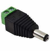
A DC Power Jack, often referred to as a DC pin, is a common electrical connector used to supply direct current (DC) power to a device or circuit. It is designed to receive a matching DC plug from an external power supply. DC power jacks are widely used in portable electronic devices, such as laptops, cameras, and small appliances, where a connection to a power source is necessary for charging or direct operation.
Explore Projects Built with DC PIN


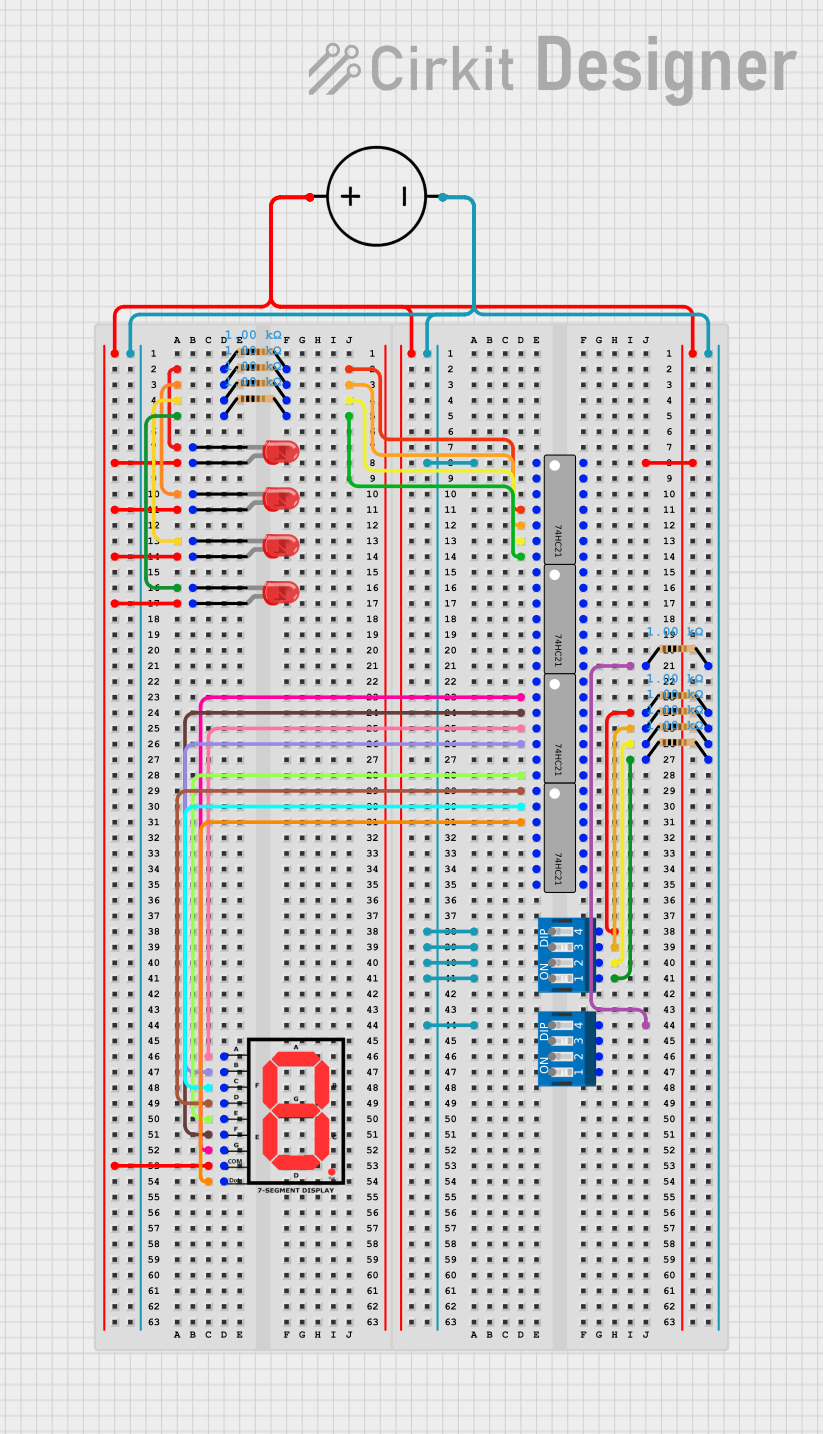
Explore Projects Built with DC PIN
Common Applications and Use Cases
- Power supply input for portable electronics
- Charging ports for battery-operated devices
- External power source connections for small appliances
- DIY electronics projects requiring external power
Technical Specifications
Key Technical Details
- Rated Voltage: The maximum voltage the DC pin can handle, typically ranging from 5V to 24V.
- Rated Current: The maximum current the DC pin can conduct, often between 1A to 5A.
- Contact Resistance: The electrical resistance between the plug and the jack, usually below 0.03 ohms.
- Insulation Resistance: The electrical resistance between the conducting parts and the outer casing, typically above 100M ohms.
- Durability: The number of insertion and removal cycles the jack can withstand without failure, often rated at 5,000 to 10,000 cycles.
Pin Configuration and Descriptions
| Pin Number | Description | Notes |
|---|---|---|
| 1 | Center Positive | Connected to the positive voltage |
| 2 | Outer Negative | Connected to ground |
Usage Instructions
How to Use the Component in a Circuit
- Identify the Polarity: Ensure the polarity of the DC power jack matches that of the power supply. The center pin is typically positive, while the outer sleeve is negative.
- Mounting: Secure the DC power jack to your device or circuit board. Some jacks are designed for PCB mounting, while others may require a panel mount.
- Soldering: Solder the connections to the appropriate points on your circuit. Use a soldering iron with an appropriate temperature setting to avoid damaging the component.
- Connection: Connect the external power supply's DC plug to the jack. Ensure a snug fit to maintain a good electrical connection.
Important Considerations and Best Practices
- Voltage and Current Ratings: Do not exceed the voltage and current ratings of the DC power jack to avoid damage.
- Polarity: Incorrect polarity can damage the connected device. Always double-check the polarity before powering up.
- Mechanical Stress: Avoid excessive force when inserting or removing the plug to prevent mechanical damage.
- Heat Management: Ensure proper heat dissipation when soldering and during operation to prevent overheating.
Troubleshooting and FAQs
Common Issues Users Might Face
- Loose Connections: If the device intermittently loses power, check for a loose plug or solder joint.
- No Power: Ensure the power supply is working and the polarity is correct. Check for any visible damage to the jack or plug.
- Overheating: If the jack overheats, it may be due to excessive current. Verify that the current draw is within the specified limits.
Solutions and Tips for Troubleshooting
- Resoldering: If connections are loose, resolder them ensuring good contact.
- Polarity Check: Use a multimeter to verify the polarity of the power supply and the jack.
- Replacement: If the jack is damaged, replace it with a new one that matches the technical specifications.
FAQs
Q: Can I use a DC power jack with an AC power source? A: No, DC power jacks are designed for DC power only. Using an AC power source can damage the component and the connected device.
Q: How do I know if the DC power jack is center positive or center negative? A: The symbol near the jack usually indicates the polarity. A plus sign (+) near the center pin indicates center positive. Always refer to the device's documentation for confirmation.
Q: What should I do if the DC power jack feels loose? A: Check the solder joints and the mechanical mounting. If necessary, resolder or tighten the mounting to ensure stability.
Example Code for Arduino UNO Connection
// Example code to demonstrate how to power an Arduino UNO using a DC power jack

void setup() {
  // Initialize digital pin LED_BUILTIN as an output.
  pinMode(LED_BUILTIN, OUTPUT);
}

void loop() {
  // Turn the LED on (HIGH is the voltage level)
  digitalWrite(LED_BUILTIN, HIGH);
  // Wait for a second
  delay(1000);
  // Turn the LED off by making the voltage LOW
  digitalWrite(LED_BUILTIN, LOW);
   // Wait for a second
  delay(1000);
}

// Note: This code assumes that the Arduino UNO is powered through its DC power jack
// with a suitable power supply that matches the Arduino's voltage and current requirements.
Remember to ensure that the power supply connected to the Arduino's DC power jack meets the board's requirements (7-12V input voltage recommended, with sufficient current capacity).