
How to Use ESP32-S3 WROOM N16R8 FREENOVE: Examples, Pinouts, and Specs
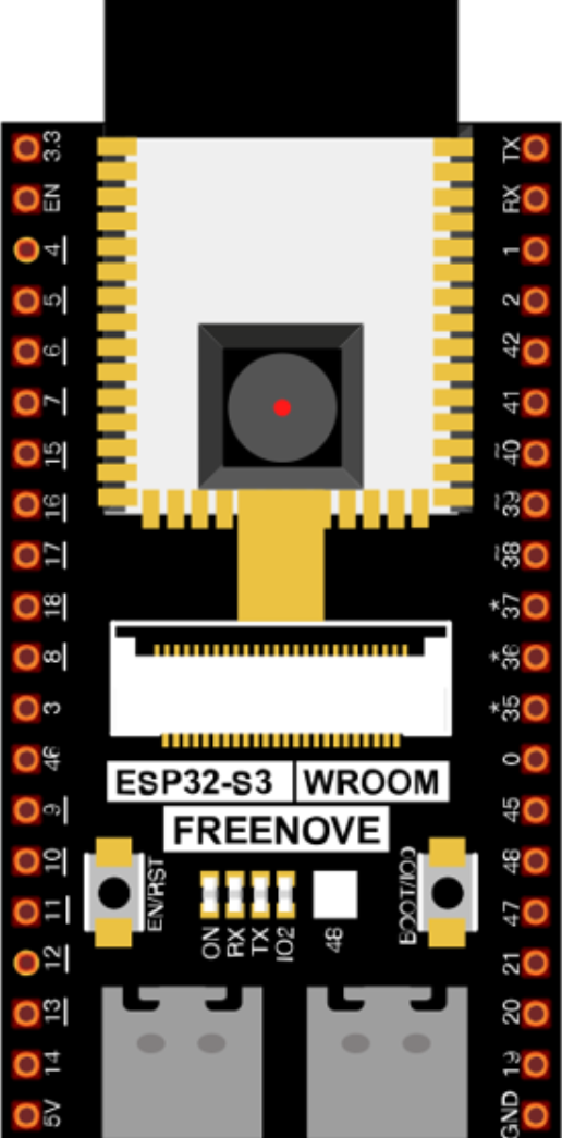
 Design with ESP32-S3 WROOM N16R8 FREENOVE in Cirkit Designer
Introduction
The ESP32-S3 WROOM N16R8 by FREENOVE is a powerful microcontroller module designed for IoT (Internet of Things) applications. It features integrated Wi-Fi and Bluetooth connectivity, making it ideal for smart devices, home automation, and industrial IoT systems. With 16MB of flash memory, 8MB of PSRAM, and a dual-core processor, this module is capable of handling complex tasks and multitasking efficiently. Its compact design and robust performance make it a popular choice for developers and hobbyists alike.
Explore Projects Built with ESP32-S3 WROOM N16R8 FREENOVE
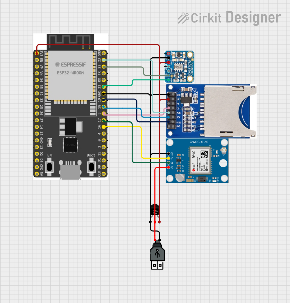 Open Project in Cirkit Designer
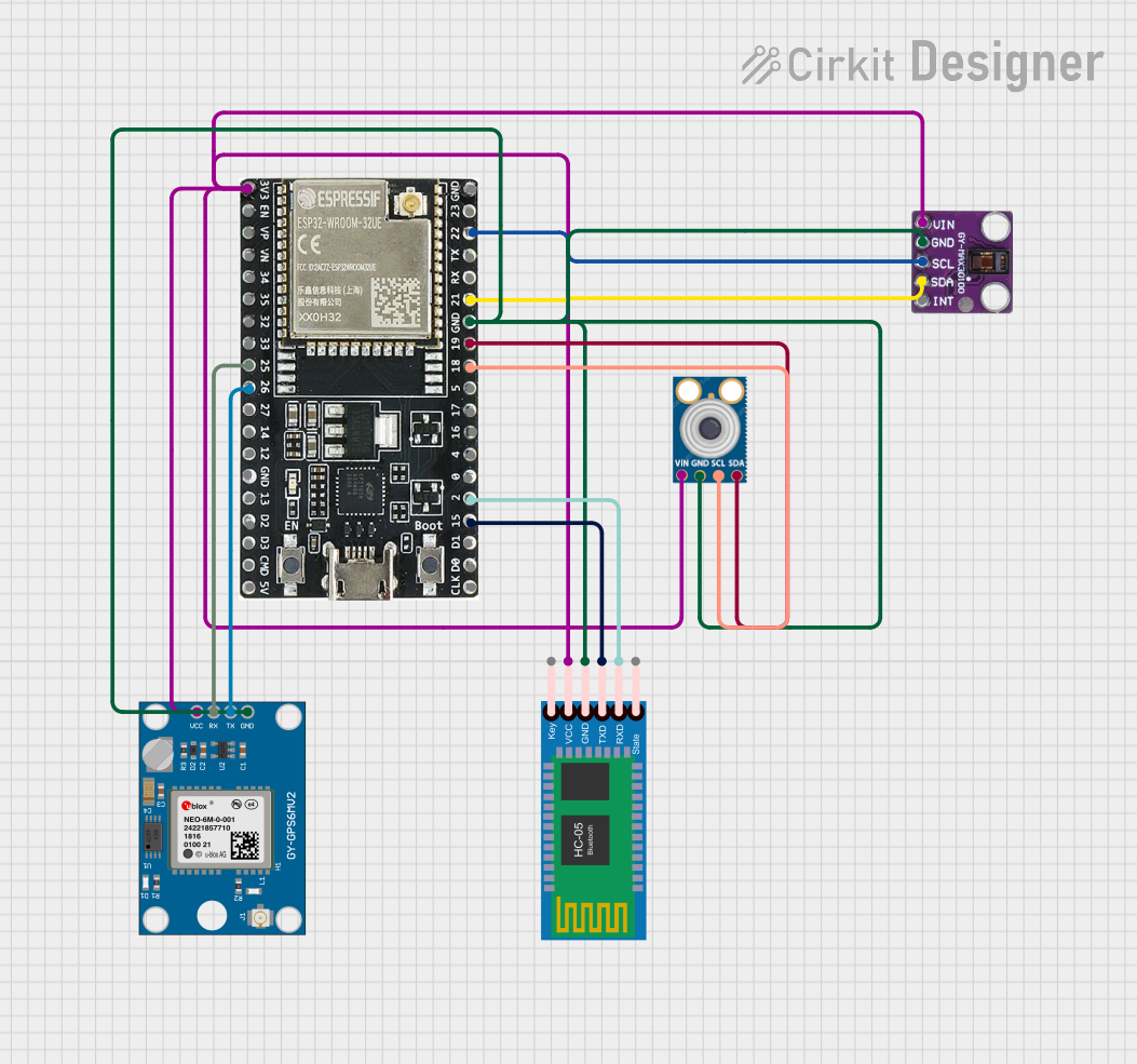 Open Project in Cirkit Designer
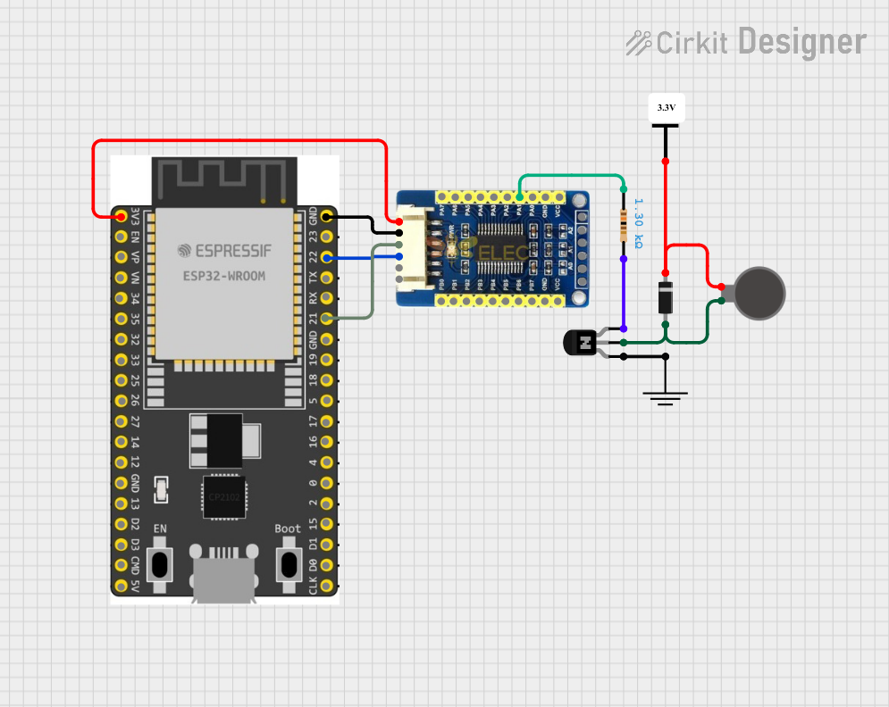 Open Project in Cirkit Designer
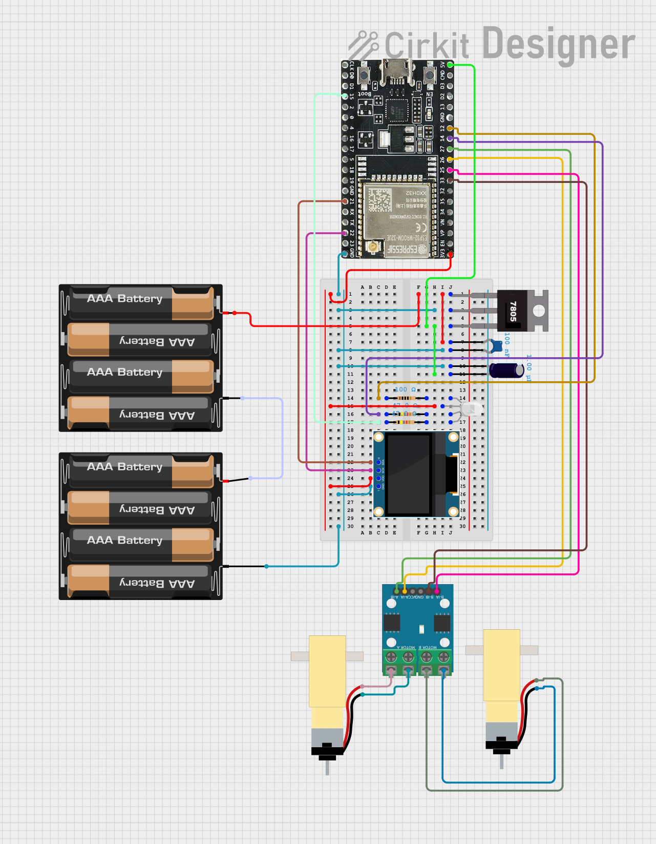 Open Project in Cirkit Designer
Explore Projects Built with ESP32-S3 WROOM N16R8 FREENOVE
Open Project in Cirkit DesignerOpen Project in Cirkit DesignerOpen Project in Cirkit DesignerOpen Project in Cirkit DesignerCommon Applications and Use Cases
- Smart home devices (e.g., smart lights, thermostats, and security systems)
- Industrial IoT systems for monitoring and control
- Wearable devices and health monitoring systems
- Robotics and automation projects
- Wireless sensor networks
- Edge computing and AI/ML applications
Technical Specifications
The ESP32-S3 WROOM N16R8 is packed with advanced features and capabilities. Below are its key technical specifications:
| Specification | Details |
|---|---|
| Manufacturer | FREENOVE |
| Microcontroller | ESP32-S3 (Xtensa® 32-bit LX7 dual-core processor) |
| Clock Speed | Up to 240 MHz |
| Flash Memory | 16MB |
| PSRAM | 8MB |
| Wi-Fi | 802.11 b/g/n (2.4 GHz) |
| Bluetooth | Bluetooth 5.0 LE (Low Energy) |
| GPIO Pins | 45 (including ADC, DAC, PWM, I2C, SPI, UART, etc.) |
| Operating Voltage | 3.3V |
| Input Voltage Range | 3.0V to 3.6V |
| Power Consumption | Ultra-low power consumption in deep sleep mode |
| Operating Temperature | -40°C to +85°C |
| Dimensions | 18 mm x 25.5 mm x 3 mm |
Pin Configuration and Descriptions
The ESP32-S3 WROOM N16R8 has a variety of pins for different functionalities. Below is a summary of the pin configuration:
| Pin Name | Type | Description |
|---|---|---|
| GPIO0 | Input/Output | General-purpose I/O, boot mode selection |
| GPIO1 | Input/Output | General-purpose I/O, UART TX |
| GPIO2 | Input/Output | General-purpose I/O, ADC, DAC |
| GPIO3 | Input/Output | General-purpose I/O, UART RX |
| GPIO4 | Input/Output | General-purpose I/O, PWM |
| GPIO5 | Input/Output | General-purpose I/O, SPI |
| EN | Input | Enable pin, active high |
| 3V3 | Power | 3.3V power supply |
| GND | Power | Ground |
Note: For a complete pinout diagram, refer to the official datasheet provided by FREENOVE.
Usage Instructions
How to Use the ESP32-S3 WROOM N16R8 in a Circuit
- Power Supply: Ensure the module is powered with a stable 3.3V supply. Avoid exceeding the input voltage range (3.0V to 3.6V).
- Connections:
- Connect the
GNDpin to the ground of your circuit. - Use the
ENpin to enable or disable the module. - Connect GPIO pins as needed for your application (e.g., sensors, actuators, or communication interfaces).
- Connect the
- Programming: The module can be programmed using the Arduino IDE or ESP-IDF (Espressif IoT Development Framework). Ensure the correct board and port are selected in your development environment.
Important Considerations and Best Practices
- Use level shifters if interfacing with 5V logic devices, as the ESP32-S3 operates at 3.3V logic levels.
- Add decoupling capacitors near the power pins to ensure stable operation.
- Avoid leaving unused GPIO pins floating; configure them as inputs with pull-up or pull-down resistors if necessary.
- Use proper antenna placement for optimal Wi-Fi and Bluetooth performance.
Example Code for Arduino UNO Integration
Below is an example of how to use the ESP32-S3 WROOM N16R8 with the Arduino IDE to blink an LED connected to GPIO2:
// Example: Blink an LED connected to GPIO2 on the ESP32-S3 WROOM N16R8

#define LED_PIN 2  // Define the GPIO pin for the LED

void setup() {
  pinMode(LED_PIN, OUTPUT);  // Set GPIO2 as an output pin
}

void loop() {
  digitalWrite(LED_PIN, HIGH);  // Turn the LED on
  delay(1000);                  // Wait for 1 second
  digitalWrite(LED_PIN, LOW);   // Turn the LED off
  delay(1000);                  // Wait for 1 second
}
Tip: Install the ESP32 board package in the Arduino IDE before uploading the code. Go to
File > Preferences, add the ESP32 board URL, and install the package via the Board Manager.
Troubleshooting and FAQs
Common Issues and Solutions
Module Not Detected in Arduino IDE:
- Ensure the correct COM port is selected.
- Install the ESP32 board package in the Arduino IDE.
- Check the USB cable for data transfer capability (some cables are power-only).
Wi-Fi Connection Fails:
- Verify the SSID and password in your code.
- Ensure the router is operating on the 2.4 GHz band (not 5 GHz).
Program Upload Fails:
- Press and hold the
BOOTbutton on the module while uploading the code. - Check for proper drivers for the USB-to-serial converter.
- Press and hold the
Overheating:
- Ensure the module is not exposed to high ambient temperatures.
- Verify that the power supply is within the recommended voltage range.
FAQs
Q: Can the ESP32-S3 WROOM N16R8 be powered by a 5V source?
A: No, the module operates at 3.3V. Use a voltage regulator or level shifter if interfacing with 5V systems.
Q: Does the module support OTA (Over-the-Air) updates?
A: Yes, the ESP32-S3 supports OTA updates, allowing you to update firmware wirelessly.
Q: How do I reset the module?
A: You can reset the module by toggling the EN pin or pressing the reset button (if available on your development board).
Q: Is the module compatible with ESP-IDF?
A: Yes, the ESP32-S3 WROOM N16R8 is fully compatible with ESP-IDF, the official development framework by Espressif.
For additional support, refer to the official FREENOVE documentation or community forums.