How to Use ESP32-S3: Examples, Pinouts, and Specs
Introduction
The ESP32-S3 is a high-performance, low-power system on a chip (SoC) manufactured by Automata. It is designed for Internet of Things (IoT) applications and features integrated Wi-Fi and Bluetooth capabilities. With its dual-core processor, enhanced AI acceleration, and a wide range of peripherals, the ESP32-S3 is ideal for complex tasks, real-time applications, and edge computing.
Explore Projects Built with ESP32-S3


Explore Projects Built with ESP32-S3
Common Applications and Use Cases
- IoT Devices: Smart home systems, industrial IoT, and connected appliances.
- AI and Machine Learning: Edge AI applications, voice recognition, and image processing.
- Wearable Devices: Fitness trackers, smartwatches, and health monitoring systems.
- Embedded Systems: Robotics, automation, and sensor networks.
- Wireless Communication: Wi-Fi and Bluetooth-enabled devices for data transfer and control.
Technical Specifications
Key Technical Details
| Parameter | Specification |
|---|---|
| Manufacturer | Automata |
| Part ID | ESP32 |
| Processor | Dual-core Xtensa® LX7 (up to 240 MHz) |
| AI Acceleration | Vector instructions for AI/ML workloads |
| Wireless Connectivity | Wi-Fi 802.11 b/g/n (2.4 GHz), Bluetooth 5.0 LE |
| Flash Memory | Up to 16 MB external flash |
| SRAM | 512 KB internal SRAM, with support for external PSRAM |
| GPIO Pins | 45 GPIOs (configurable for various functions) |
| Operating Voltage | 3.0V to 3.6V |
| Power Consumption | Ultra-low power modes for battery-powered applications |
| Peripherals | SPI, I2C, UART, ADC, DAC, PWM, SDIO, CAN, Ethernet, and more |
| Operating Temperature | -40°C to +85°C |
| Package | QFN48 or QFN68 |
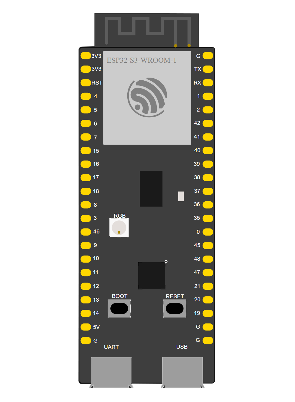
Pin Configuration and Descriptions
The ESP32-S3 has a flexible pinout with up to 45 GPIOs. Below is a summary of key pins:
| Pin Name | Function | Description |
|---|---|---|
| VDD | Power Supply | Connect to 3.3V power supply. |
| GND | Ground | Connect to ground. |
| GPIO0 | Boot Mode Selection | Used for boot mode selection during programming. |
| GPIO1-45 | General Purpose I/O | Configurable for digital I/O, ADC, DAC, PWM, I2C, SPI, UART, etc. |
| EN | Chip Enable | Active high. Pull low to reset the chip. |
| TXD0/RXD0 | UART0 TX/RX | Default UART for programming and debugging. |
| ADC1/ADC2 | Analog-to-Digital Converter Pins | Used for analog input (12-bit resolution). |
| DAC1/DAC2 | Digital-to-Analog Converter Pins | Used for analog output. |
| MTMS/MTDI | JTAG Debugging Pins | Used for debugging and development. |
Usage Instructions
How to Use the ESP32-S3 in a Circuit
- Power Supply: Provide a stable 3.3V power supply to the VDD pin. Ensure proper decoupling capacitors are placed near the power pins.
- Programming: Use a USB-to-UART converter to connect the ESP32-S3 to your computer. Connect:
- TXD0 to the RX pin of the converter.
- RXD0 to the TX pin of the converter.
- GPIO0 to GND during programming to enable boot mode.
- GPIO Configuration: Configure GPIO pins as needed for digital I/O, ADC, DAC, or communication protocols (SPI, I2C, UART).
- Antenna: Ensure proper placement of the onboard antenna or connect an external antenna for optimal wireless performance.
Important Considerations and Best Practices
- Power Management: Use the ultra-low power modes for battery-powered applications to extend battery life.
- Decoupling: Place decoupling capacitors (e.g., 0.1 µF) close to the power pins to reduce noise.
- Antenna Placement: Avoid placing metal objects near the antenna to prevent signal interference.
- Programming Mode: Ensure GPIO0 is pulled low during programming and released after flashing the firmware.
- Heat Dissipation: For high-performance applications, ensure proper heat dissipation to avoid thermal throttling.
Example: Connecting ESP32-S3 to Arduino IDE
The ESP32-S3 can be programmed using the Arduino IDE. Follow these steps:
- Install the ESP32 Board Manager in the Arduino IDE.
- Select the ESP32-S3 board from the Tools menu.
- Connect the ESP32-S3 to your computer via a USB-to-UART converter.
- Use the following example code to blink an LED connected to GPIO2:
// Example: Blink an LED connected to GPIO2

#define LED_PIN 2  // Define the GPIO pin for the LED

void setup() {
  pinMode(LED_PIN, OUTPUT);  // Set GPIO2 as an output pin
}

void loop() {
  digitalWrite(LED_PIN, HIGH);  // Turn the LED on
  delay(1000);                  // Wait for 1 second
  digitalWrite(LED_PIN, LOW);   // Turn the LED off
  delay(1000);                  // Wait for 1 second
}
Troubleshooting and FAQs
Common Issues and Solutions
ESP32-S3 Not Detected by Computer
- Ensure the USB-to-UART driver is installed on your computer.
- Check the connections between the ESP32-S3 and the USB-to-UART converter.
- Verify that GPIO0 is pulled low during programming.
Wi-Fi Connection Fails
- Ensure the correct SSID and password are used in your code.
- Check for interference from other devices operating on the 2.4 GHz band.
High Power Consumption
- Use the ultra-low power modes for battery-powered applications.
- Disable unused peripherals to reduce power consumption.
Program Upload Fails
- Verify that the correct board and COM port are selected in the Arduino IDE.
- Ensure GPIO0 is connected to GND during programming.
FAQs
Q: Can the ESP32-S3 be powered with 5V?
A: No, the ESP32-S3 operates at 3.3V. Using 5V can damage the chip. Use a voltage regulator if needed.
Q: How many devices can the ESP32-S3 connect to via Bluetooth?
A: The ESP32-S3 supports Bluetooth 5.0 LE and can connect to multiple devices, depending on the application.
Q: Does the ESP32-S3 support over-the-air (OTA) updates?
A: Yes, the ESP32-S3 supports OTA updates, allowing firmware to be updated wirelessly.
Q: Can I use the ESP32-S3 for AI applications?
A: Yes, the ESP32-S3 includes vector instructions optimized for AI/ML workloads, making it suitable for edge AI applications.
This concludes the documentation for the ESP32-S3. For further assistance, refer to the official datasheet or contact Automata support.