How to Use 12v Solenoid: Examples, Pinouts, and Specs
Introduction
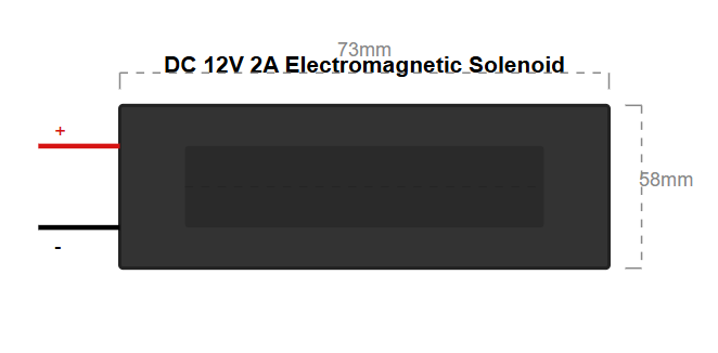
The 12V solenoid is an electromechanical device that converts electrical energy into linear motion. It operates by using an electromagnetic coil to create a magnetic field, which moves a plunger or armature. This motion is typically used to control mechanical systems such as valves, actuators, or locks.
Explore Projects Built with 12v Solenoid
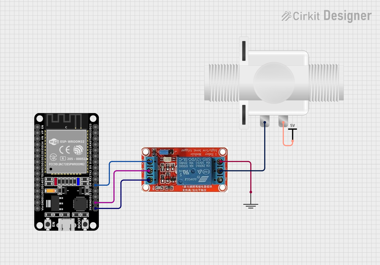
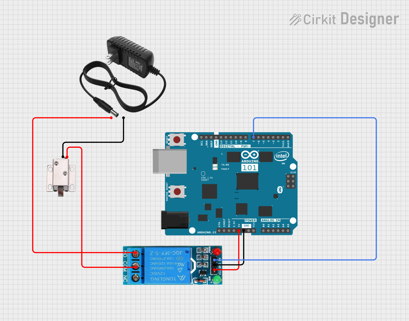
Explore Projects Built with 12v Solenoid
Common Applications and Use Cases
- Automotive systems: Fuel injectors, door locks, and starter motors.
- Industrial automation: Controlling pneumatic or hydraulic valves.
- Home appliances: Door latches in washing machines or dishwashers.
- DIY projects: Robotics, automated mechanisms, and Arduino-based systems.
Technical Specifications
The following table outlines the key technical details of a standard 12V solenoid:
| Parameter | Value |
|---|---|
| Operating Voltage | 12V DC |
| Current Consumption | 0.5A to 1.5A (depending on model) |
| Power Rating | 6W to 18W |
| Stroke Length | 5mm to 30mm (varies by model) |
| Force | 2N to 50N (varies by model) |
| Coil Resistance | 8Ω to 24Ω |
| Duty Cycle | 10% to 100% (model-dependent) |
| Operating Temperature | -20°C to 60°C |
Pin Configuration and Descriptions
The 12V solenoid typically has two terminals for electrical connections:
| Pin | Description |
|---|---|
| + | Positive terminal (connect to 12V) |
| - | Negative terminal (connect to GND) |
Usage Instructions
How to Use the 12V Solenoid in a Circuit
- Power Supply: Ensure you have a stable 12V DC power source capable of supplying sufficient current for the solenoid.
- Driver Circuit: Use a transistor or MOSFET to control the solenoid, as it typically requires more current than a microcontroller can provide directly.
- Flyback Diode: Always connect a flyback diode across the solenoid terminals to protect the circuit from voltage spikes caused by the collapsing magnetic field when the solenoid is turned off.
- Control Signal: Use a microcontroller (e.g., Arduino UNO) or a manual switch to control the solenoid's operation.
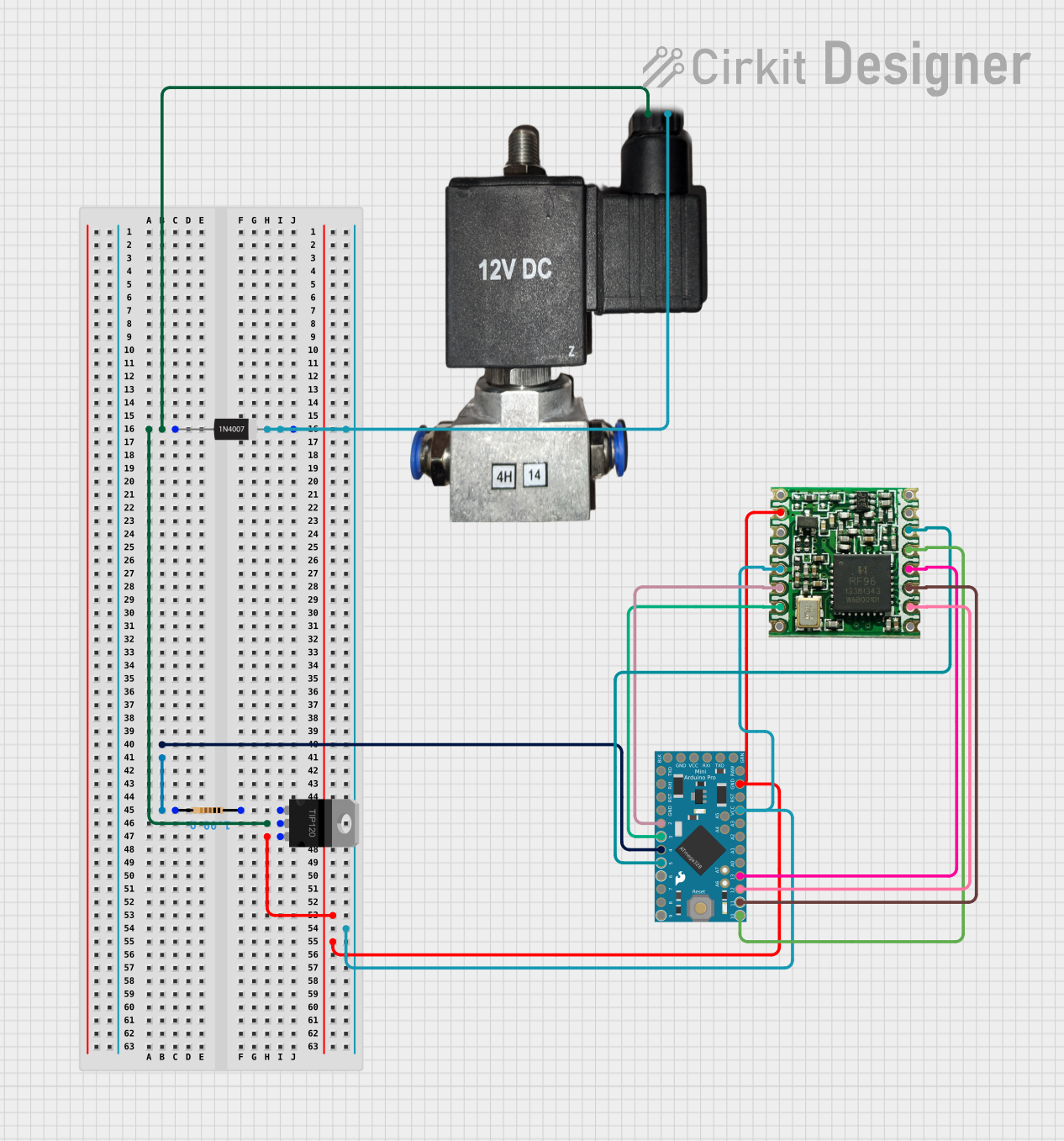
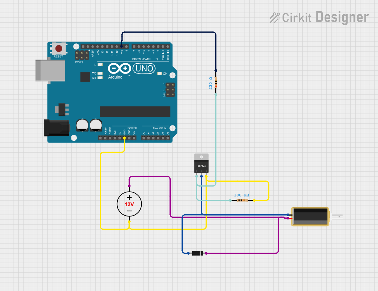
Example Circuit with Arduino UNO
Below is an example of how to connect and control a 12V solenoid using an Arduino UNO and an NPN transistor (e.g., 2N2222):
Components Required:
- 12V solenoid
- Arduino UNO
- NPN transistor (e.g., 2N2222)
- Flyback diode (e.g., 1N4007)
- 1kΩ resistor
- 12V DC power supply
Circuit Diagram:
- Connect the solenoid's positive terminal to the 12V power supply.
- Connect the solenoid's negative terminal to the collector of the NPN transistor.
- Place the flyback diode across the solenoid terminals (cathode to positive, anode to negative).
- Connect the emitter of the transistor to GND.
- Connect a 1kΩ resistor between the Arduino digital pin (e.g., D9) and the base of the transistor.
- Connect the Arduino GND to the power supply GND.
Arduino Code:
// Arduino code to control a 12V solenoid
// Connect the solenoid control pin to Arduino pin D9

const int solenoidPin = 9; // Pin connected to the transistor base

void setup() {
  pinMode(solenoidPin, OUTPUT); // Set the solenoid pin as an output
}

void loop() {
  digitalWrite(solenoidPin, HIGH); // Activate the solenoid
  delay(1000);                     // Keep it on for 1 second
  digitalWrite(solenoidPin, LOW);  // Deactivate the solenoid
  delay(1000);                     // Wait for 1 second
}
Important Considerations and Best Practices
- Power Supply: Ensure the power supply can handle the solenoid's current requirements.
- Heat Management: If the solenoid operates continuously, monitor its temperature to avoid overheating.
- Duty Cycle: Check the solenoid's duty cycle rating to prevent damage from prolonged activation.
- Flyback Diode: Always use a flyback diode to protect your circuit from voltage spikes.
Troubleshooting and FAQs
Common Issues and Solutions
Solenoid Not Activating:
- Check the power supply voltage and current rating.
- Verify the connections and ensure the transistor or MOSFET is functioning correctly.
- Ensure the Arduino or control signal is providing the correct output.
Overheating:
- Reduce the activation time or duty cycle.
- Ensure proper ventilation or cooling for the solenoid.
Voltage Spikes Damaging Components:
- Confirm that a flyback diode is installed correctly across the solenoid terminals.
Weak or No Linear Motion:
- Check for obstructions in the solenoid's plunger mechanism.
- Verify that the solenoid is receiving the correct voltage and current.
FAQs
Q: Can I power the solenoid directly from the Arduino?
A: No, the Arduino cannot supply enough current to drive the solenoid. Use a transistor or MOSFET as a driver.
Q: What happens if I don't use a flyback diode?
A: Without a flyback diode, the voltage spike generated when the solenoid turns off can damage other components in the circuit.
Q: Can I use a 12V solenoid with a 9V power supply?
A: While it may work at reduced performance, it is not recommended as the solenoid may not generate enough force or may fail to operate reliably.
Q: How do I calculate the required current for my solenoid?
A: Use Ohm's Law: Current (I) = Voltage (V) / Resistance (R). For example, if the solenoid has a coil resistance of 12Ω, the current required is 12V / 12Ω = 1A.