How to Use CD4060: Examples, Pinouts, and Specs
Introduction
The CD4060, manufactured by Motorola, is a 14-stage ripple carry binary counter and oscillator. This versatile component integrates a built-in oscillator circuit and can count up to (2^{14}), making it ideal for timing, frequency division, and clock pulse generation. Its ability to operate over a wide voltage range and its low power consumption make it a popular choice in both hobbyist and professional electronic projects.
Explore Projects Built with CD4060


Explore Projects Built with CD4060
Common Applications
- Frequency division and clock generation
- Timers and delay circuits
- Pulse generation for digital circuits
- Oscillator circuits for microcontroller-based systems
- LED blinking and other periodic signal generation tasks
Technical Specifications
The following table outlines the key technical details of the CD4060:
| Parameter | Value |
|---|---|
| Manufacturer | Motorola |
| Part ID | 14-Stage Ripple Carry Binary Counters |
| Supply Voltage (V(_{DD})) | 3V to 15V |
| Maximum Clock Frequency | 2 MHz (at 10V supply) |
| Output Voltage (High) | V(_{DD}) - 0.05V (typical) |
| Output Voltage (Low) | 0.05V (typical) |
| Operating Temperature Range | -55°C to +125°C |
| Power Dissipation | 500 mW (maximum) |
| Propagation Delay | 200 ns (typical at 10V) |
Pin Configuration and Descriptions
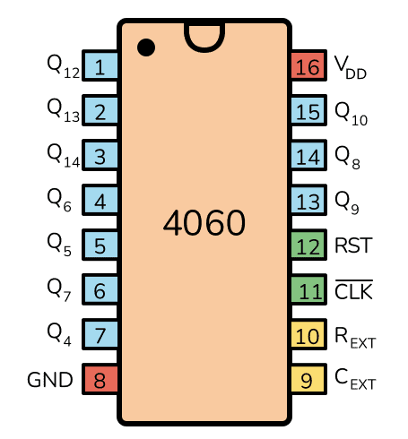
The CD4060 is a 16-pin IC with the following pinout:
| Pin Number | Pin Name | Description |
|---|---|---|
| 1 | Q4 | Output of the 4th stage of the counter |
| 2 | Q5 | Output of the 5th stage of the counter |
| 3 | Q6 | Output of the 6th stage of the counter |
| 4 | Q7 | Output of the 7th stage of the counter |
| 5 | Q8 | Output of the 8th stage of the counter |
| 6 | Q9 | Output of the 9th stage of the counter |
| 7 | Q10 | Output of the 10th stage of the counter |
| 8 | GND | Ground (0V reference) |
| 9 | Q12 | Output of the 12th stage of the counter |
| 10 | Q13 | Output of the 13th stage of the counter |
| 11 | Q14 | Output of the 14th stage of the counter |
| 12 | RESET | Resets the counter to zero when pulled HIGH |
| 13 | OSC INHIBIT | Disables the oscillator when pulled HIGH |
| 14 | OSC OUT | Oscillator output |
| 15 | OSC IN | Oscillator input for external RC or crystal configuration |
| 16 | V(_{DD}) | Positive supply voltage |
Usage Instructions
How to Use the CD4060 in a Circuit
- Power Supply: Connect pin 16 (V(_{DD})) to the positive supply voltage (3V to 15V) and pin 8 (GND) to ground.
- Oscillator Configuration:
- Use pins 9 (OSC IN), 10 (OSC OUT), and 11 (OSC INHIBIT) to configure the internal oscillator.
- Connect an external resistor and capacitor to set the desired oscillation frequency. For example:
- Resistor (R): 10 kΩ to 1 MΩ
- Capacitor (C): 10 pF to 1 µF
- The oscillation frequency can be approximated using the formula: [ f = \frac{1}{2.2 \cdot R \cdot C} ]
- Counter Outputs: Use the Q4 to Q14 pins to access the binary counter outputs. Each output represents a divided frequency of the oscillator signal.
- Reset Function: To reset the counter, momentarily pull the RESET pin (pin 12) HIGH.
- Oscillator Inhibit: Pull the OSC INHIBIT pin (pin 13) HIGH to disable the oscillator.
Example Circuit with Arduino UNO
The CD4060 can be used with an Arduino UNO to generate a clock signal or divide frequencies. Below is an example of how to use the CD4060 to blink an LED at a divided frequency:
Circuit Connections
- Connect V(_{DD}) (pin 16) to the Arduino's 5V pin.
- Connect GND (pin 8) to the Arduino's GND.
- Connect a 100 kΩ resistor between OSC IN (pin 15) and OSC OUT (pin 14).
- Connect a 10 nF capacitor between OSC IN (pin 15) and GND.
- Connect Q4 (pin 1) to an LED with a current-limiting resistor.
Arduino Code
// This code demonstrates how to monitor the CD4060's output using an Arduino.
// The LED connected to Q4 will blink at a frequency determined by the RC network.

void setup() {
  pinMode(2, INPUT); // Connect Q4 (pin 1 of CD4060) to Arduino pin 2
  pinMode(13, OUTPUT); // Built-in LED for debugging
}

void loop() {
  int state = digitalRead(2); // Read the state of Q4
  digitalWrite(13, state); // Reflect the state on the built-in LED
}
Important Considerations
- Ensure the resistor and capacitor values are chosen to achieve the desired oscillation frequency.
- Avoid exceeding the maximum supply voltage (15V) to prevent damage to the IC.
- Use decoupling capacitors (e.g., 0.1 µF) near the power supply pins to reduce noise.
Troubleshooting and FAQs
Common Issues
No Oscillation:
- Cause: Incorrect resistor or capacitor values.
- Solution: Verify the RC network and ensure the values are within the recommended range.
Counter Not Resetting:
- Cause: RESET pin not properly connected or pulled HIGH.
- Solution: Check the RESET pin connection and ensure it is momentarily pulled HIGH to reset the counter.
Outputs Not Changing:
- Cause: Oscillator not functioning or OSC INHIBIT pin is HIGH.
- Solution: Verify the oscillator circuit and ensure the OSC INHIBIT pin is LOW.
FAQs
Q1: Can I use a crystal oscillator with the CD4060?
Yes, the CD4060 supports crystal oscillators. Connect the crystal between OSC IN (pin 15) and OSC OUT (pin 14), and add appropriate capacitors to ground.
Q2: What is the maximum frequency the CD4060 can handle?
The maximum clock frequency is approximately 2 MHz when powered at 10V.
Q3: Can I cascade multiple CD4060 ICs?
Yes, you can cascade multiple CD4060 ICs by connecting the output of one IC to the clock input of another for extended counting capabilities.
This concludes the documentation for the CD4060.