How to Use ESP32 - CAM: Examples, Pinouts, and Specs
Introduction
The ESP32-CAM is a low-cost development board that combines the powerful ESP32 microcontroller with integrated Wi-Fi and Bluetooth capabilities, along with a camera module. This compact and versatile board is ideal for IoT applications, enabling image capture, video streaming, and wireless communication. Its small form factor and rich feature set make it a popular choice for projects such as home automation, surveillance systems, and AI-powered image recognition.
Explore Projects Built with ESP32 - CAM


Explore Projects Built with ESP32 - CAM
Common Applications and Use Cases
- Wireless video streaming and surveillance systems
- Smart home automation with image recognition
- IoT devices requiring camera functionality
- AI-based object detection and tracking
- Remote monitoring and control systems
Technical Specifications
Key Technical Details
- Microcontroller: ESP32-D0WDQ6
- Wireless Connectivity: Wi-Fi 802.11 b/g/n and Bluetooth 4.2
- Camera Module: OV2640 (2MP resolution)
- Flash Memory: 4 MB (PSRAM)
- Operating Voltage: 3.3V
- Input Voltage Range: 5V (via micro-USB or 5V pin)
- GPIO Pins: 9 available for user applications
- Image Output Formats: JPEG, BMP, GRAYSCALE
- Power Consumption: ~160 mA in active mode
- Dimensions: 27 x 40.5 mm
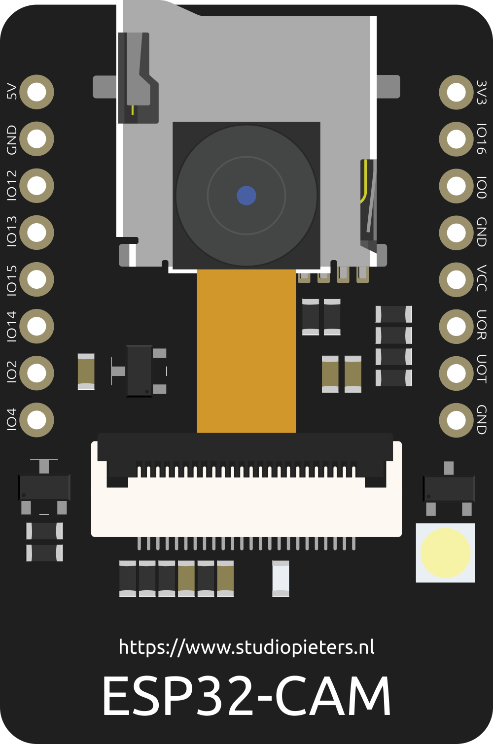
Pin Configuration and Descriptions
The ESP32-CAM has a total of 16 pins. Below is the pinout and description:
| Pin | Name | Description |
|---|---|---|
| 1 | GND | Ground connection |
| 2 | 5V | Power input (5V) |
| 3 | 3.3V | Power output (3.3V) |
| 4 | GPIO0 | General-purpose I/O pin; used for boot mode selection |
| 5 | GPIO1 (U0TXD) | UART0 TX pin; used for serial communication |
| 6 | GPIO3 (U0RXD) | UART0 RX pin; used for serial communication |
| 7 | GPIO16 | General-purpose I/O pin |
| 8 | GPIO17 | General-purpose I/O pin |
| 9 | GPIO12 | General-purpose I/O pin; connected to the microSD card interface (DATA2) |
| 10 | GPIO13 | General-purpose I/O pin; connected to the microSD card interface (DATA3) |
| 11 | GPIO14 | General-purpose I/O pin; connected to the microSD card interface (CLK) |
| 12 | GPIO15 | General-purpose I/O pin; connected to the microSD card interface (CMD) |
| 13 | GPIO2 | General-purpose I/O pin; connected to the onboard LED |
| 14 | GPIO4 | General-purpose I/O pin; connected to the camera module |
| 15 | GPIO5 | General-purpose I/O pin; connected to the camera module |
| 16 | RESET | Reset pin; used to restart the ESP32-CAM |
Usage Instructions
How to Use the ESP32-CAM in a Circuit
Powering the Board:
- Supply 5V to the
5Vpin or via the micro-USB port. Ensure the power source can provide at least 500 mA. - Connect the
GNDpin to the ground of your circuit.
- Supply 5V to the
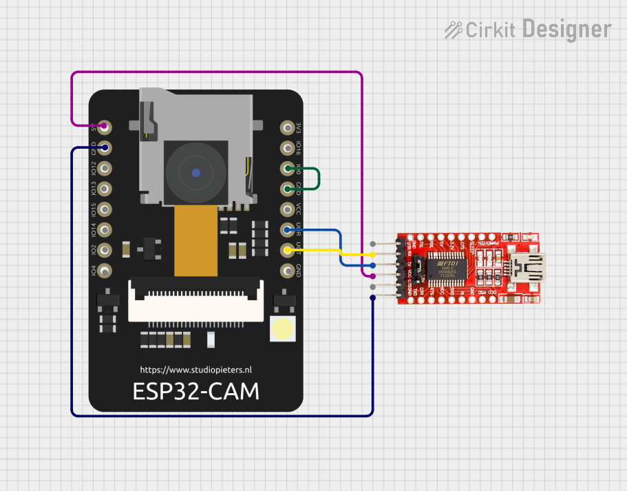
Programming the ESP32-CAM:
- The ESP32-CAM does not have a built-in USB-to-serial converter. Use an external FTDI programmer or USB-to-serial adapter.
- Connect the FTDI adapter as follows:
- FTDI
TX→ ESP32-CAMU0RXD(GPIO3) - FTDI
RX→ ESP32-CAMU0TXD(GPIO1) - FTDI
GND→ ESP32-CAMGND - FTDI
5V→ ESP32-CAM5V
- FTDI
- Set the FTDI adapter to 5V mode.
- To enter programming mode, connect GPIO0 to GND and press the reset button.
Uploading Code:
- Use the Arduino IDE or ESP-IDF to upload code. Select "AI-Thinker ESP32-CAM" as the board in the Arduino IDE.
Connecting Peripherals:
- Use the GPIO pins to connect sensors, actuators, or other peripherals. Be mindful of the 3.3V logic level.
Important Considerations and Best Practices
- Power Supply: Ensure a stable 5V power supply to avoid unexpected resets or malfunctions.
- Heat Management: The ESP32-CAM can get warm during operation. Consider adding a heatsink for prolonged use.
- Antenna Selection: The board has an onboard PCB antenna and a connector for an external antenna. Use a jumper to select the desired antenna.
- Boot Mode: Always disconnect GPIO0 from GND after uploading code to boot the ESP32-CAM normally.
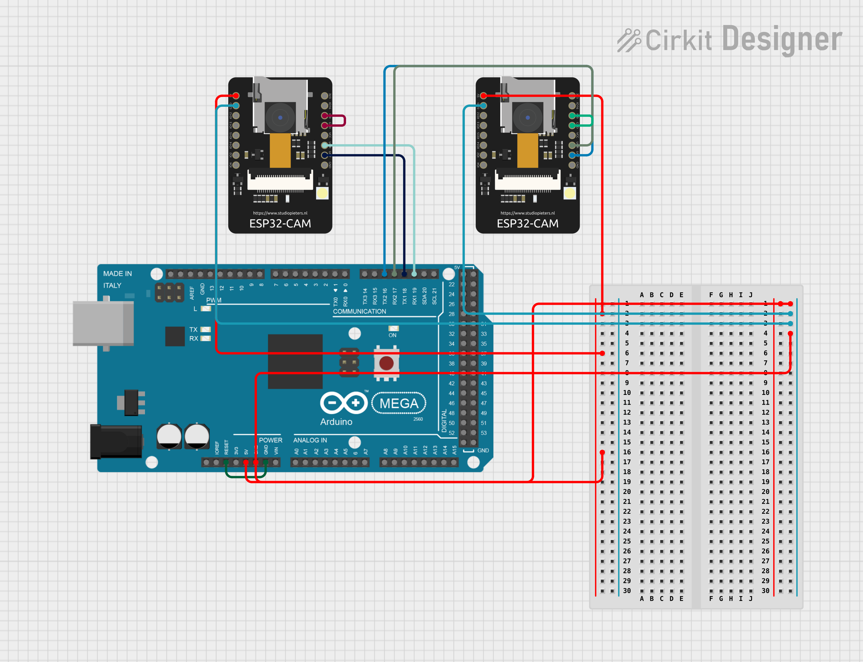
Example Code for Arduino UNO Integration
Below is an example of how to use the ESP32-CAM to capture and stream video:
#include <WiFi.h>
#include <esp_camera.h>

// Replace with your network credentials
const char* ssid = "Your_SSID";
const char* password = "Your_PASSWORD";

// Camera configuration
#define PWDN_GPIO_NUM    -1
#define RESET_GPIO_NUM   -1
#define XCLK_GPIO_NUM     0
#define SIOD_GPIO_NUM    26
#define SIOC_GPIO_NUM    27
#define Y9_GPIO_NUM      35
#define Y8_GPIO_NUM      34
#define Y7_GPIO_NUM      39
#define Y6_GPIO_NUM      36
#define Y5_GPIO_NUM      21
#define Y4_GPIO_NUM      19
#define Y3_GPIO_NUM      18
#define Y2_GPIO_NUM       5
#define VSYNC_GPIO_NUM   25
#define HREF_GPIO_NUM    23
#define PCLK_GPIO_NUM    22

void startCameraServer();

void setup() {
  Serial.begin(115200);
  WiFi.begin(ssid, password);

  // Wait for Wi-Fi connection
  while (WiFi.status() != WL_CONNECTED) {
    delay(500);
    Serial.print(".");
  }
  Serial.println("\nWiFi connected");

  // Camera initialization
  camera_config_t config;
  config.ledc_channel = LEDC_CHANNEL_0;
  config.ledc_timer = LEDC_TIMER_0;
  config.pin_d0 = Y2_GPIO_NUM;
  config.pin_d1 = Y3_GPIO_NUM;
  config.pin_d2 = Y4_GPIO_NUM;
  config.pin_d3 = Y5_GPIO_NUM;
  config.pin_d4 = Y6_GPIO_NUM;
  config.pin_d5 = Y7_GPIO_NUM;
  config.pin_d6 = Y8_GPIO_NUM;
  config.pin_d7 = Y9_GPIO_NUM;
  config.pin_xclk = XCLK_GPIO_NUM;
  config.pin_pclk = PCLK_GPIO_NUM;
  config.pin_vsync = VSYNC_GPIO_NUM;
  config.pin_href = HREF_GPIO_NUM;
  config.pin_sscb_sda = SIOD_GPIO_NUM;
  config.pin_sscb_scl = SIOC_GPIO_NUM;
  config.pin_pwdn = PWDN_GPIO_NUM;
  config.pin_reset = RESET_GPIO_NUM;
  config.xclk_freq_hz = 20000000;
  config.pixel_format = PIXFORMAT_JPEG;

  if (!esp_camera_init(&config)) {
    Serial.println("Camera initialized successfully");
  } else {
    Serial.println("Camera initialization failed");
    return;
  }

  startCameraServer();
}

void loop() {
  // Main loop does nothing; camera server handles requests
}
Troubleshooting and FAQs
Common Issues and Solutions
ESP32-CAM Not Detected by the Computer:
- Ensure the FTDI adapter is connected correctly.
- Check that GPIO0 is connected to GND during programming.
Frequent Resets or Instability:
- Use a stable 5V power supply with sufficient current (at least 500 mA).
- Avoid powering the ESP32-CAM through the FTDI adapter for extended periods.
Camera Initialization Failed:
- Verify the camera module is securely connected to the ESP32-CAM board.
- Ensure the correct camera model (e.g., OV2640) is selected in the code.
Wi-Fi Connection Issues:
- Double-check the SSID and password in the code.
- Ensure the Wi-Fi network is within range and not overloaded.
FAQs
Can I use the ESP32-CAM without a camera module?
Yes, the ESP32-CAM can function as a standard ESP32 development board without the camera.What is the maximum resolution supported by the camera?
The OV2640 camera module supports up to 1600x1200 (UXGA) resolution.Can I use an external antenna?
Yes, you can connect an