How to Use PCA9685: Examples, Pinouts, and Specs
Introduction
The PCA9685 is a 16-channel, 12-bit PWM (Pulse Width Modulation) controller designed for applications requiring precise control of multiple outputs. It is commonly used for controlling servos, LEDs, and other devices that require PWM signals. The PCA9685 communicates via the I2C protocol, making it easy to interface with microcontrollers such as Arduino, Raspberry Pi, and others. Its ability to control up to 16 channels simultaneously makes it ideal for robotics, lighting systems, and other multi-output applications.
Explore Projects Built with PCA9685
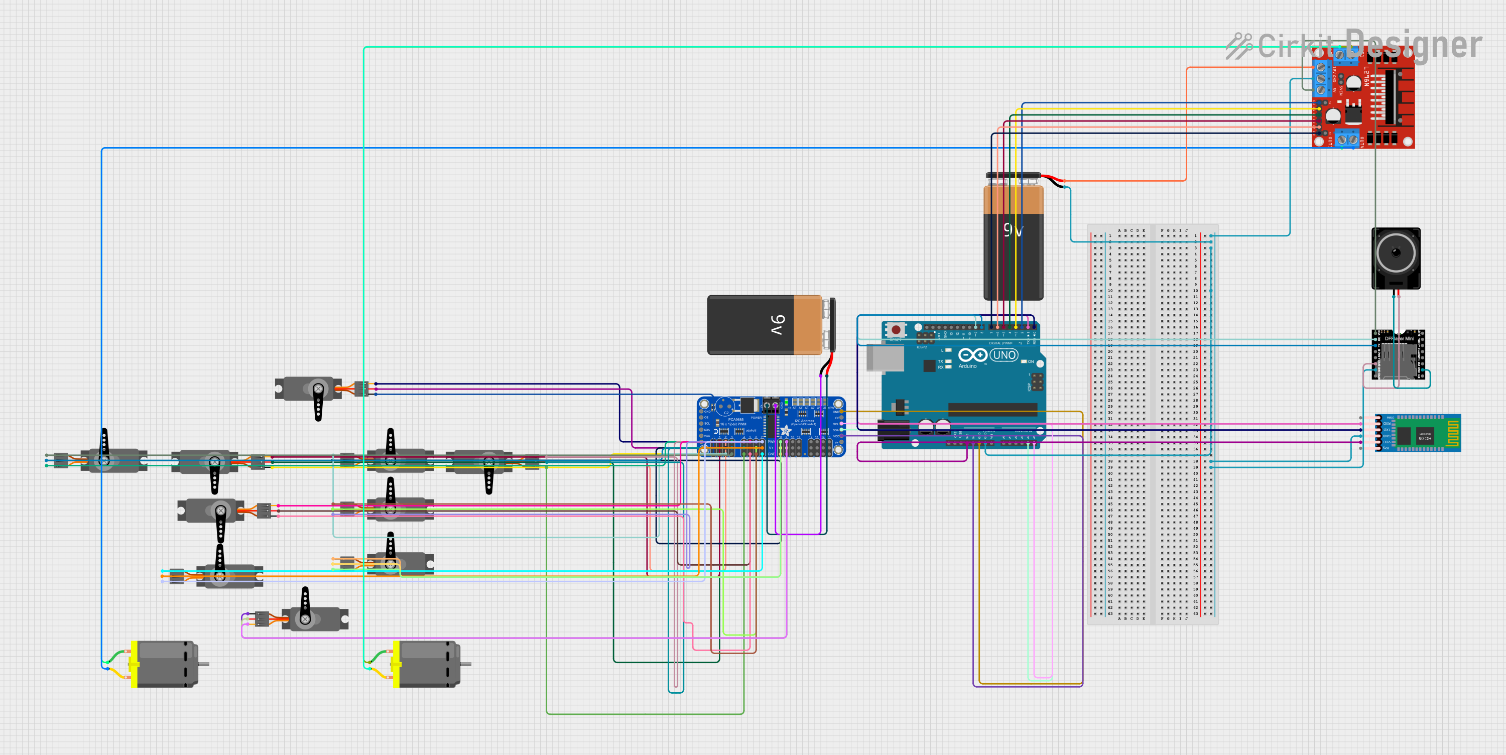

Explore Projects Built with PCA9685
Common Applications
- Servo motor control in robotics
- LED dimming and lighting effects
- Motor speed control
- Signal generation for various devices
- Animatronics and hobby projects
Technical Specifications
The PCA9685 offers robust features for PWM signal generation. Below are its key technical specifications:
| Parameter | Value |
|---|---|
| Operating Voltage | 2.3V to 5.5V |
| Logic Voltage | 3.3V or 5V (I2C logic level compatible) |
| PWM Resolution | 12-bit (4096 steps) |
| Number of Channels | 16 |
| Maximum Output Current | 25mA per channel |
| Maximum Frequency | 1.6 kHz |
| Communication Protocol | I2C |
| Default I2C Address | 0x40 (configurable via address pins) |
| Operating Temperature | -40°C to +85°C |
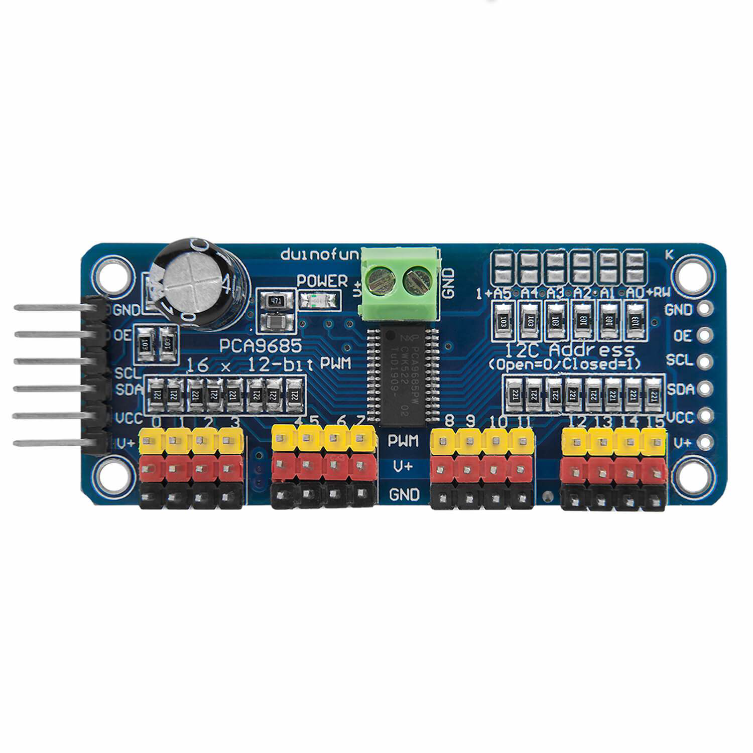
Pin Configuration
The PCA9685 is typically available in a 28-pin package. Below is the pin configuration:
| Pin Name | Type | Description |
|---|---|---|
| VCC | Power | Power supply input (2.3V to 5.5V) |
| GND | Ground | Ground connection |
| SDA | Input/Output | I2C data line |
| SCL | Input | I2C clock line |
| OE | Input | Output enable (active low) |
| A0–A5 | Input | I2C address selection pins |
| LED0–LED15 | Output | PWM output channels |
| EXTCLK | Input | External clock input (optional) |
| V+ | Power | External power for driving LEDs or servos |
Usage Instructions
The PCA9685 is straightforward to use in a circuit. Below are the steps and considerations for using it effectively:
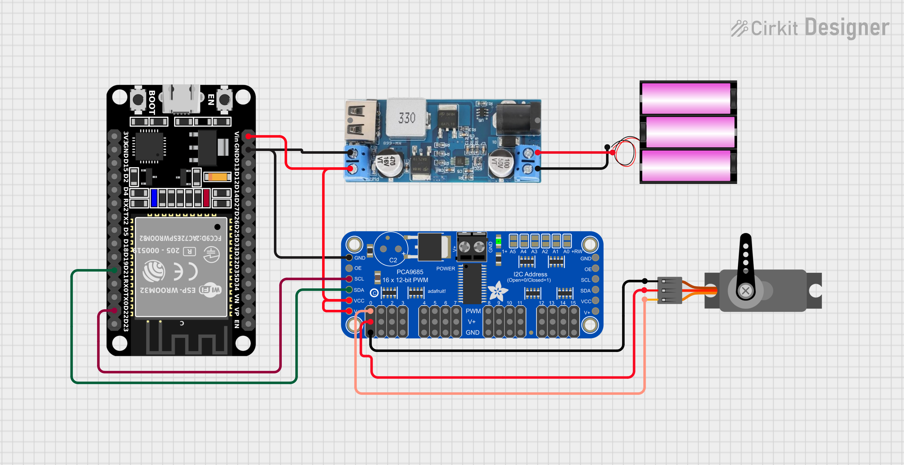
Connecting the PCA9685
- Power Supply: Connect the VCC pin to a 3.3V or 5V power source, and GND to ground.
- I2C Communication: Connect the SDA and SCL pins to the corresponding I2C pins on your microcontroller. Use pull-up resistors (typically 4.7kΩ) if not already present on your board.
- Output Devices: Connect servos, LEDs, or other devices to the LED0–LED15 pins. If driving high-power devices, connect an external power source to the V+ pin.
- Address Configuration: Use the A0–A5 pins to set the I2C address if multiple PCA9685 modules are used in the same system.
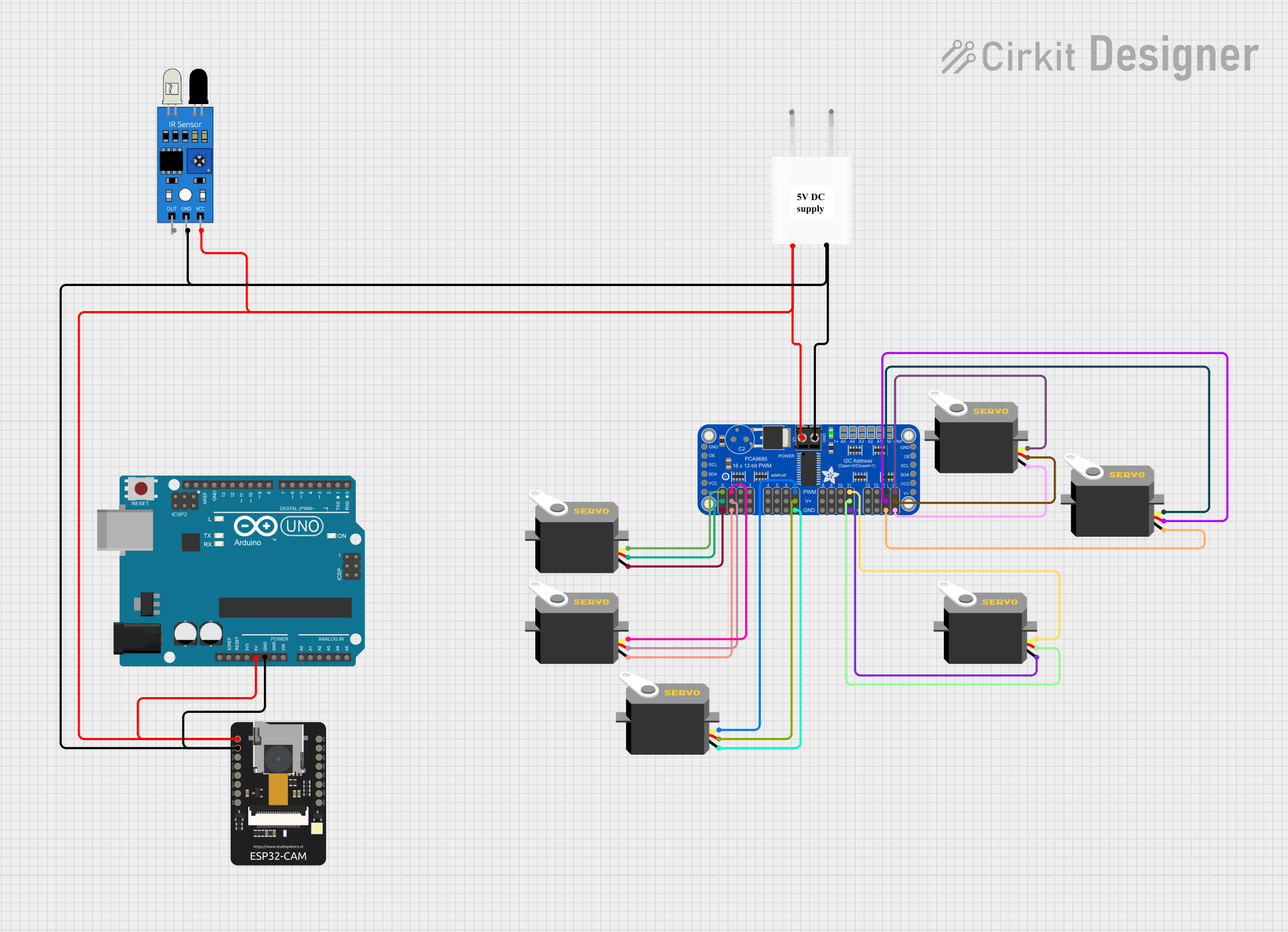
Example: Using PCA9685 with Arduino UNO
Below is an example of how to control a servo motor using the PCA9685 and Arduino UNO:
Circuit Diagram
- Connect VCC and GND of the PCA9685 to 5V and GND of the Arduino.
- Connect SDA and SCL of the PCA9685 to A4 and A5 of the Arduino (for older boards) or to the dedicated SDA and SCL pins (for newer boards).
- Connect the servo motor to one of the PWM output pins (e.g., LED0).
Code Example
#include <Wire.h>
#include <Adafruit_PWMServoDriver.h>

// Create an instance of the PCA9685 driver
Adafruit_PWMServoDriver pwm = Adafruit_PWMServoDriver();

void setup() {
  // Initialize I2C communication
  pwm.begin();

  // Set the PWM frequency to 50 Hz (common for servos)
  pwm.setPWMFreq(50);
}

void loop() {
  // Set servo on channel 0 to a specific position
  // 0 corresponds to 0 degrees, 4095 corresponds to 180 degrees
  int servoMin = 150; // Minimum pulse length for 0 degrees
  int servoMax = 600; // Maximum pulse length for 180 degrees

  // Move servo to 90 degrees
  int pulseLength = (servoMin + servoMax) / 2;
  pwm.setPWM(0, 0, pulseLength);

  delay(1000); // Wait for 1 second
}
Best Practices
- Use decoupling capacitors near the VCC pin to reduce noise.
- Avoid exceeding the maximum current rating of 25mA per channel.
- If driving high-power devices, ensure the external power supply connected to V+ can handle the load.
- Use proper heat dissipation methods if the module operates at high currents for extended periods.
Troubleshooting and FAQs
Common Issues
No Response from PCA9685
- Cause: Incorrect I2C address or wiring.
- Solution: Verify the I2C address and ensure SDA/SCL connections are correct. Check for pull-up resistors.
PWM Outputs Not Working
- Cause: Incorrect frequency or pulse width settings.
- Solution: Ensure the PWM frequency is set correctly (e.g., 50 Hz for servos). Verify pulse width values.
Overheating
- Cause: Exceeding current limits or insufficient cooling.
- Solution: Reduce the load on each channel or improve heat dissipation.
Flickering LEDs
- Cause: Insufficient power supply or incorrect PWM settings.
- Solution: Use a stable power source and verify PWM frequency and duty cycle.
FAQs
Can I use multiple PCA9685 modules in one system?
- Yes, you can connect up to 62 modules by configuring the A0–A5 address pins.
What is the maximum number of servos I can control?
- Each PCA9685 can control up to 16 servos. With multiple modules, you can control hundreds of servos.
Can I use the PCA9685 with a 3.3V microcontroller?
- Yes, the PCA9685 is compatible with both 3.3V and 5V logic levels.
What is the default I2C address of the PCA9685?
- The default address is 0x40, but it can be changed using the A0–A5 pins.
By following this documentation, you can effectively integrate the PCA9685 into your projects for precise PWM control.