How to Use CD drive BLDC motor: Examples, Pinouts, and Specs
Introduction
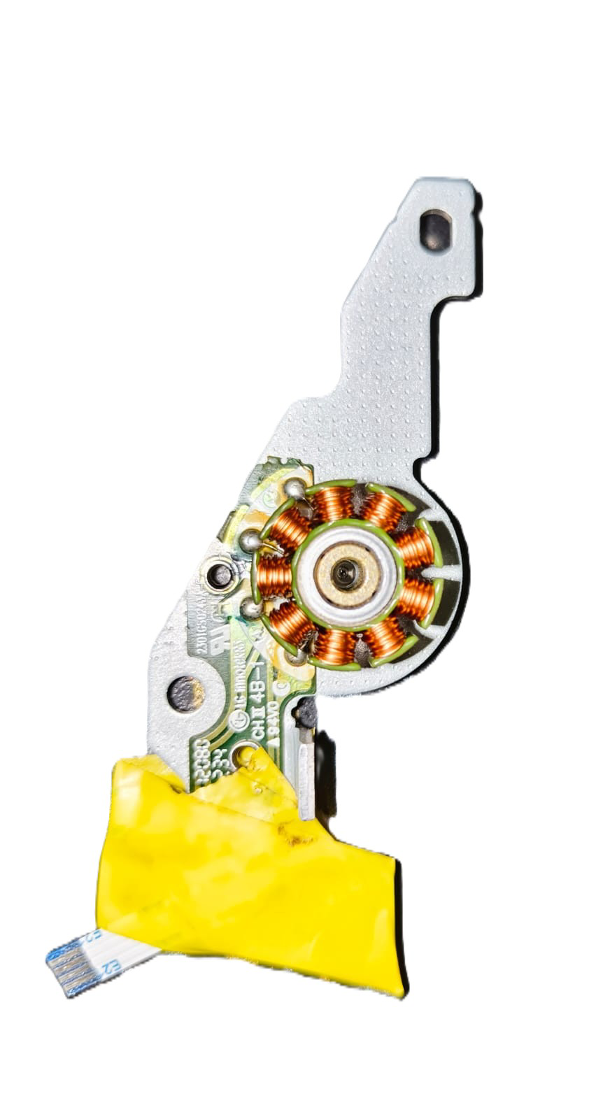
The CD Drive BLDC (Brushless DC) Motor, manufactured by LG Electronics (Part ID: CD drive BLDC motor), is a compact and efficient motor designed for precise rotational control. This motor is commonly used in CD/DVD drives to spin optical discs at varying speeds for data reading and writing. Its brushless design ensures durability, low noise, and minimal maintenance, making it ideal for applications requiring high reliability and precision.
Explore Projects Built with CD drive BLDC motor
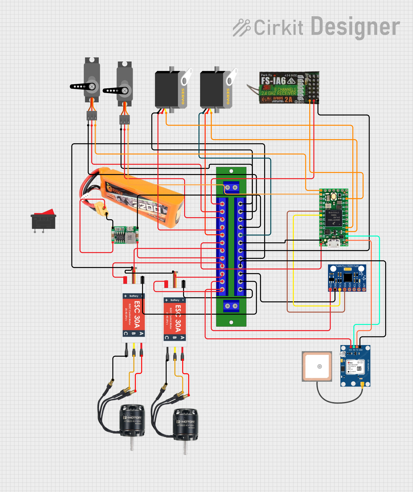

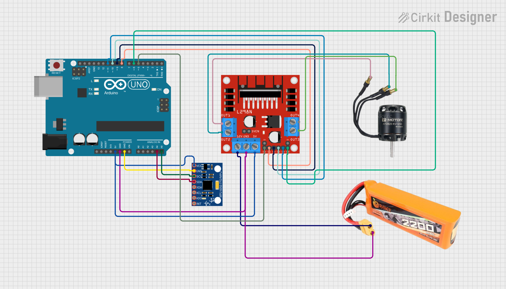
Explore Projects Built with CD drive BLDC motor
Common Applications and Use Cases
- Optical disc drives (CD/DVD/Blu-ray players and writers)
- Small robotics and precision mechanisms
- Compact cooling systems
- Educational and DIY electronics projects
Technical Specifications
Key Technical Details
| Parameter | Specification |
|---|---|
| Manufacturer | LG Electronics |
| Part ID | CD drive BLDC motor |
| Motor Type | Brushless DC (BLDC) |
| Operating Voltage | 5V to 12V |
| Rated Current | 200mA to 500mA (depending on load) |
| Speed | Up to 10,000 RPM |
| Torque | Low torque, optimized for light loads |
| Dimensions | Diameter: ~30mm, Height: ~10mm |
| Weight | ~15g |
| Connector Type | 3-pin (U, V, W phases) |
| Control Method | Electronic speed controller (ESC) or microcontroller |
Pin Configuration and Descriptions
The CD Drive BLDC Motor typically has three output wires for its three-phase operation. These wires are connected to an ESC or a microcontroller for proper control.
| Pin/Wire Name | Description |
|---|---|
| U (Phase 1) | First phase of the motor windings |
| V (Phase 2) | Second phase of the motor windings |
| W (Phase 3) | Third phase of the motor windings |
Note: Some motors may include an additional wire for a Hall sensor or tachometer feedback, but this is not standard for all models.
Usage Instructions
How to Use the Component in a Circuit
- Power Supply: Ensure the motor is powered with a voltage between 5V and 12V, depending on the desired speed and torque. Use a regulated power supply to avoid damage.
- Controller: Connect the motor to an ESC or a microcontroller capable of generating three-phase PWM signals. The ESC simplifies control by handling the phase switching internally.
- Connections:
- Connect the U, V, and W wires of the motor to the corresponding outputs of the ESC.
- If using a microcontroller, ensure it can generate the required PWM signals for the motor phases.
- Control Signal: Use a PWM signal or a dedicated motor control library to adjust the motor speed and direction.
Important Considerations and Best Practices
- Back-EMF Protection: Use a motor driver or ESC with built-in protection against back-EMF to prevent damage to the control circuitry.
- Heat Management: Avoid prolonged operation at high speeds or under heavy loads to prevent overheating.
- Mounting: Secure the motor firmly to minimize vibrations and ensure smooth operation.
- Startup Sequence: BLDC motors require a specific startup sequence to determine rotor position. Use an ESC or a microcontroller with BLDC support to handle this.
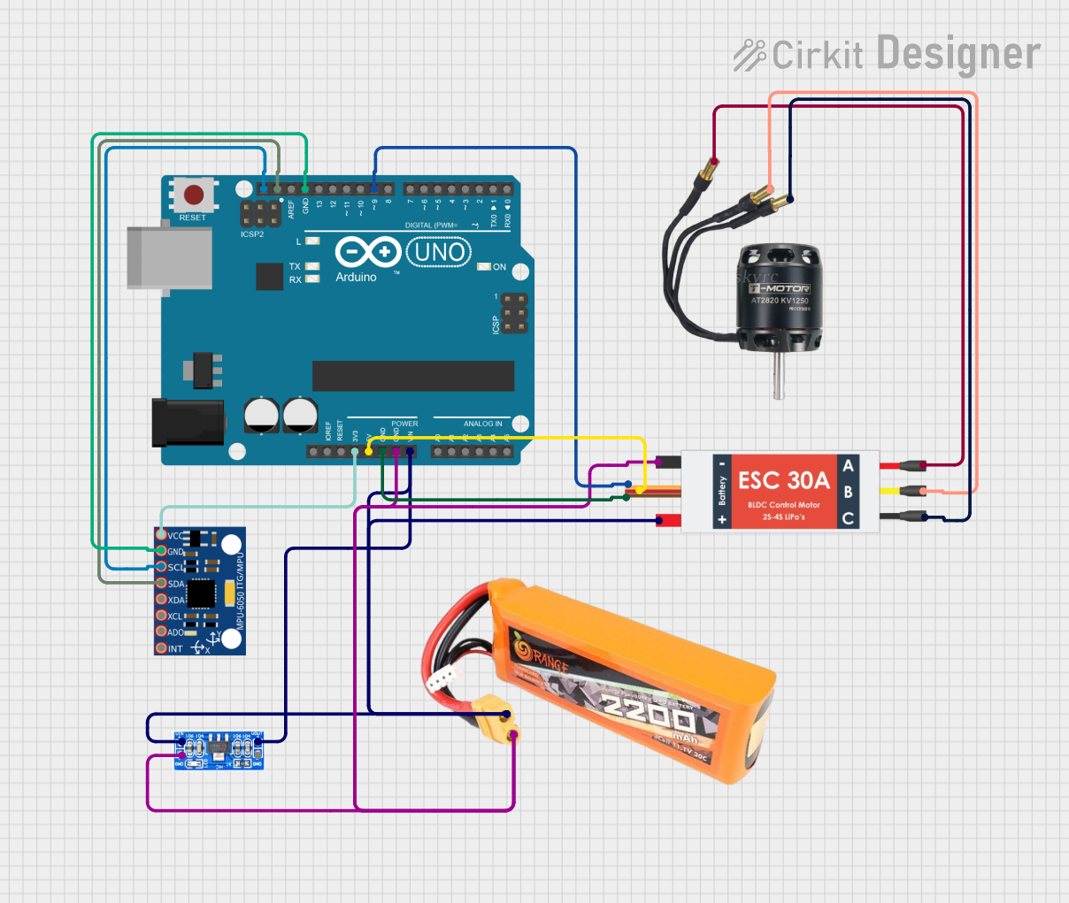
Example: Using the Motor with an Arduino UNO
Below is an example of controlling the CD Drive BLDC Motor using an Arduino UNO and an ESC.
/*
  Example: Controlling a CD Drive BLDC Motor with Arduino UNO and ESC
  - Connect the ESC signal wire to Arduino pin 9.
  - Connect the ESC power input to a 5V-12V power supply.
  - Ensure the motor's U, V, W wires are connected to the ESC.
*/

#include <Servo.h> // Library to generate PWM signals for the ESC

Servo esc; // Create a Servo object to control the ESC

void setup() {
  esc.attach(9); // Attach ESC signal wire to pin 9
  esc.writeMicroseconds(1000); // Send minimum throttle signal to arm the ESC
  delay(2000); // Wait for the ESC to initialize
}

void loop() {
  esc.writeMicroseconds(1500); // Set throttle to 50% (adjust for speed control)
  delay(5000); // Run motor for 5 seconds

  esc.writeMicroseconds(1000); // Stop the motor
  delay(2000); // Wait before restarting
}
Note: Always refer to the ESC's documentation for specific arming and control requirements.
Troubleshooting and FAQs
Common Issues and Solutions
Motor Does Not Spin:
- Cause: Incorrect wiring or insufficient power supply.
- Solution: Verify the connections between the motor, ESC, and power supply. Ensure the ESC is properly armed.
Motor Vibrates but Does Not Rotate:
- Cause: Incorrect phase wiring or missing startup sequence.
- Solution: Check the U, V, and W wire connections. Use an ESC or microcontroller with BLDC support.
Overheating:
- Cause: Prolonged operation at high speeds or excessive load.
- Solution: Reduce the load or speed. Ensure proper ventilation and cooling.
Noisy Operation:
- Cause: Loose mounting or damaged bearings.
- Solution: Secure the motor firmly and inspect for mechanical damage.
FAQs
Can I run the motor without an ESC? No, a BLDC motor requires precise phase switching, which is typically handled by an ESC or a microcontroller with BLDC support.
What is the maximum speed of the motor? The motor can achieve speeds up to 10,000 RPM, depending on the voltage and load.
Can I use this motor for high-torque applications? No, this motor is designed for low-torque, high-speed applications such as spinning optical discs.
Is the motor compatible with other microcontrollers? Yes, the motor can be controlled with any microcontroller capable of generating three-phase PWM signals or interfacing with an ESC.
By following this documentation, users can effectively integrate the CD Drive BLDC Motor into their projects and troubleshoot common issues.