
How to Use AD7745: Examples, Pinouts, and Specs
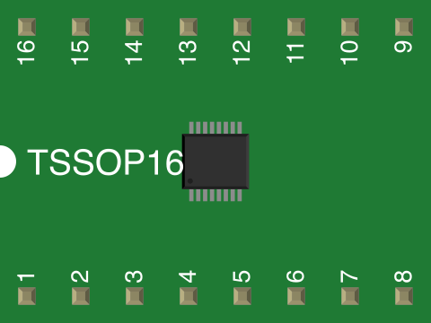
 Design with AD7745 in Cirkit Designer
Introduction
The AD7745 is a high-precision capacitive-to-digital converter (CDC) manufactured by Analog Devices. It is designed to measure small changes in capacitance with high accuracy and resolution. The AD7745 features a low-noise architecture and is ideal for applications requiring precise capacitive sensing.
Explore Projects Built with AD7745
 Open Project in Cirkit Designer
 Open Project in Cirkit Designer
 Open Project in Cirkit Designer
 Open Project in Cirkit Designer
Explore Projects Built with AD7745
Open Project in Cirkit DesignerOpen Project in Cirkit DesignerOpen Project in Cirkit DesignerOpen Project in Cirkit DesignerCommon Applications
- Touch Sensing: Used in touch-sensitive interfaces for consumer electronics.
- Liquid Level Detection: Ideal for non-contact liquid level measurement in industrial and medical applications.
- Proximity Sensing: Used in proximity detection systems for automation and security.
- Environmental Monitoring: Suitable for humidity and pressure sensing when paired with appropriate sensors.
Technical Specifications
The following table outlines the key technical specifications of the AD7745:
| Parameter | Value |
|---|---|
| Supply Voltage (VDD) | 2.7 V to 5.25 V |
| Capacitance Measurement Range | ±4 pF (with 17-bit resolution) |
| Capacitance Resolution | 4 aF (attofarads) |
| Interface | I²C (2-wire serial interface) |
| Operating Temperature Range | -40°C to +85°C |
| Power Consumption | 1 mA (typical) at 3.3 V |
| Package | 16-lead TSSOP (AD7745BRUZ) |
Pin Configuration and Descriptions
The AD7745 is available in a 16-lead TSSOP package. The pin configuration and descriptions are as follows:
| Pin Number | Pin Name | Description |
|---|---|---|
| 1 | VDD | Positive power supply (2.7 V to 5.25 V). |
| 2 | GND | Ground reference. |
| 3 | SCL | I²C clock line. |
| 4 | SDA | I²C data line. |
| 5 | CAPDAC1 | Capacitive input with optional digital-to-analog converter (DAC) offset. |
| 6 | CAPDAC2 | Secondary capacitive input with DAC offset. |
| 7 | EXC1 | Excitation output for capacitive sensor. |
| 8 | EXC2 | Secondary excitation output for capacitive sensor. |
| 9 | NC | No connection (leave unconnected). |
| 10 | NC | No connection (leave unconnected). |
| 11 | ADDR | I²C address selection pin. |
| 12 | NC | No connection (leave unconnected). |
| 13 | NC | No connection (leave unconnected). |
| 14 | NC | No connection (leave unconnected). |
| 15 | NC | No connection (leave unconnected). |
| 16 | NC | No connection (leave unconnected). |
Usage Instructions
How to Use the AD7745 in a Circuit
- Power Supply: Connect the VDD pin to a regulated power supply (2.7 V to 5.25 V) and the GND pin to the ground.
- Capacitive Sensor Connection: Attach the capacitive sensor to the CAPDAC1 and CAPDAC2 pins. Use the EXC1 and EXC2 pins to provide excitation signals to the sensor.
- I²C Communication: Connect the SCL and SDA pins to the corresponding I²C lines of your microcontroller. Use pull-up resistors (typically 4.7 kΩ) on both lines.
- I²C Address Selection: Configure the I²C address using the ADDR pin. This allows multiple AD7745 devices to share the same I²C bus.
- Bypass Capacitor: Place a 0.1 µF ceramic capacitor close to the VDD pin for power supply decoupling.
Important Considerations
- Capacitive Sensor Design: Ensure the sensor is designed to operate within the ±4 pF range of the AD7745 for optimal performance.
- PCB Layout: Minimize noise by keeping the capacitive sensor traces short and away from high-frequency signals.
- I²C Pull-Up Resistors: Use appropriate pull-up resistor values for the I²C lines based on the bus capacitance and operating speed.
Example Code for Arduino UNO
The following example demonstrates how to interface the AD7745 with an Arduino UNO using the I²C protocol:
#include <Wire.h>

// AD7745 I²C address (default is 0x48, depending on ADDR pin configuration)
#define AD7745_ADDRESS 0x48

void setup() {
  Wire.begin(); // Initialize I²C communication
  Serial.begin(9600); // Initialize serial communication for debugging

  // Configure AD7745 (example: set to continuous conversion mode)
  Wire.beginTransmission(AD7745_ADDRESS);
  Wire.write(0x07); // Write to the configuration register
  Wire.write(0x30); // Continuous conversion mode, default settings
  Wire.endTransmission();

  Serial.println("AD7745 initialized.");
}

void loop() {
  // Read capacitance data from AD7745
  Wire.beginTransmission(AD7745_ADDRESS);
  Wire.write(0x01); // Point to the capacitance data register
  Wire.endTransmission();

  Wire.requestFrom(AD7745_ADDRESS, 3); // Request 3 bytes of data
  if (Wire.available() == 3) {
    uint8_t msb = Wire.read(); // Most significant byte
    uint8_t lsb = Wire.read(); // Least significant byte
    uint8_t status = Wire.read(); // Status byte (optional)

    // Combine MSB and LSB to get the raw capacitance value
    int16_t capacitance = (msb << 8) | lsb;

    // Print the raw capacitance value
    Serial.print("Capacitance: ");
    Serial.println(capacitance);
  }

  delay(1000); // Wait 1 second before the next reading
}
Troubleshooting and FAQs
Common Issues
No Response from AD7745 on I²C Bus
- Cause: Incorrect I²C address or wiring.
- Solution: Verify the ADDR pin configuration and ensure proper connections to the SCL and SDA lines.
Inaccurate Capacitance Measurements
- Cause: Noise or improper sensor design.
- Solution: Minimize noise by improving PCB layout and shielding the sensor. Ensure the sensor operates within the ±4 pF range.
Device Overheating
- Cause: Excessive supply voltage or incorrect connections.
- Solution: Ensure the supply voltage is within the 2.7 V to 5.25 V range and check all connections.
FAQs
Can the AD7745 measure differential capacitance?
- Yes, the AD7745 can measure differential capacitance using its CAPDAC1 and CAPDAC2 inputs.
What is the maximum I²C speed supported by the AD7745?
- The AD7745 supports I²C speeds up to 400 kHz (Fast Mode).
Can I use the AD7745 with a 5 V microcontroller?
- Yes, the AD7745 is compatible with 5 V systems as long as the supply voltage (VDD) is within the specified range.
How do I calibrate the AD7745?
- Calibration can be performed by adjusting the CAPDAC settings to offset any baseline capacitance.
By following this documentation, users can effectively integrate the AD7745 into their projects for high-precision capacitive sensing applications.