How to Use Fan: Examples, Pinouts, and Specs
Introduction
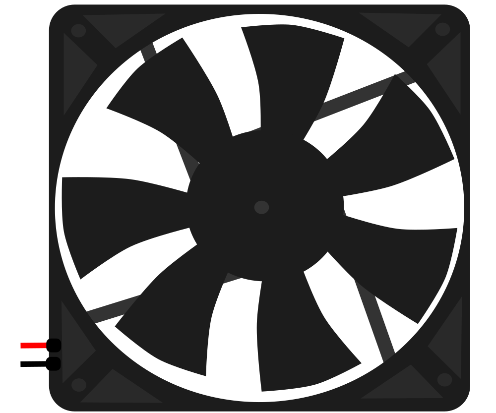
A fan is an electromechanical device designed to move air or other gases. It operates using rotating blades or impellers to generate airflow, typically for cooling purposes. Fans are essential in electronic circuits to dissipate heat and prevent overheating of components, which can lead to failure or reduced performance. They are commonly found in computer systems, power supplies, and other electronic devices where thermal management is crucial.
Explore Projects Built with Fan


Explore Projects Built with Fan
Common Applications and Use Cases
- Cooling computer CPUs and GPUs
- Ventilation in power supply units
- Air circulation in enclosed electronic systems
- Thermal management in amplifiers and audio equipment
- Cooling in LED lighting systems
Technical Specifications
Key Technical Details
- Voltage Rating: The voltage at which the fan is designed to operate.
- Current Rating: The amount of current the fan will draw at its rated voltage.
- Power Consumption: The power the fan uses, typically in watts.
- Speed: Measured in revolutions per minute (RPM), indicating how fast the blades rotate.
- Airflow: The volume of air moved by the fan, usually measured in cubic feet per minute (CFM).
- Noise Level: The sound level generated by the fan, measured in decibels (dB).
- Bearing Type: The type of bearing used in the fan, which affects lifespan and noise (e.g., sleeve, ball).
- Life Expectancy: The expected operational lifespan of the fan, often given in hours.
Pin Configuration and Descriptions
| Pin Number | Description | Notes |
|---|---|---|
| 1 | Positive Voltage (V+) | Connect to power supply (+) |
| 2 | Ground (GND) | Connect to power supply (-) |
| 3 | Tachometer Signal | Optional, for RPM feedback |
| 4 | PWM Control Signal | Optional, for speed control |
Usage Instructions
How to Use the Fan in a Circuit
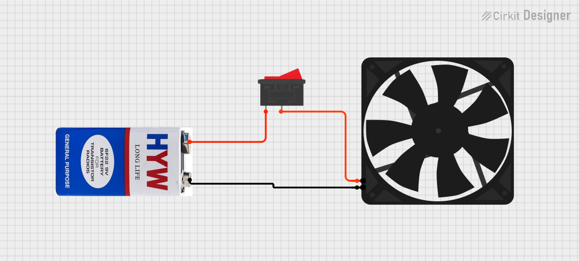
- Power Connection: Connect the positive voltage pin to the positive terminal of your power supply and the ground pin to the negative terminal.
- Speed Control (if available): If your fan supports PWM control, connect the PWM control signal pin to a PWM-capable output on your microcontroller.
- Tachometer Feedback (if available): Connect the tachometer signal pin to an input on your microcontroller to monitor fan speed.
Important Considerations and Best Practices
- Ensure the fan's voltage rating matches your power supply.
- Do not exceed the current rating of the fan to prevent damage.
- Provide adequate space for airflow and do not obstruct the fan inlet or outlet.
- Use appropriate wire gauge for the fan's current draw.
- Secure the fan to prevent vibrations and noise.
- Consider using a fan with a higher airflow rating than needed for better cooling with lower noise.
Troubleshooting and FAQs
Common Issues
- Fan not spinning: Check power connections and verify that the supply voltage is within the fan's rated voltage.
- Noisy operation: Ensure the fan is securely mounted and that nothing is obstructing the blades.
- Insufficient cooling: Verify that the fan's airflow direction is correct and that it's not being impeded.
Solutions and Tips for Troubleshooting
- If the fan is not starting, try connecting it directly to the power supply to rule out control circuit issues.
- For noise issues, inspect the fan for dust buildup and clean it if necessary.
- Ensure that the fan's airflow complements the natural convection currents in the device.
FAQs
Q: Can I control the speed of the fan? A: Yes, if your fan has a PWM control pin, you can adjust the speed using a PWM signal.
Q: What is the purpose of the tachometer signal? A: The tachometer signal provides feedback on the fan's speed, which can be used for monitoring or closed-loop control.
Q: How do I reverse the airflow direction of the fan? A: The airflow direction is fixed based on the fan's design. Reversing the power connections will not reverse the airflow.
Example Arduino Code for PWM Fan Control
// Define the PWM pin connected to the fan
const int fanPWMpin = 3;

void setup() {
  // Set the PWM pin as an output
  pinMode(fanPWMpin, OUTPUT);
}

void loop() {
  // Set the fan speed to 50% duty cycle
  analogWrite(fanPWMpin, 128); // 128 out of 255 is approximately 50%

  // Add your code here to adjust the fan speed as needed
}
Note: The above code assumes that the fan is connected to a PWM-capable pin on the Arduino UNO and that the fan supports PWM control. Adjust the duty cycle value in analogWrite to control the fan speed.