
How to Use FAN: Examples, Pinouts, and Specs
 Design with FAN in Cirkit Designer
Introduction
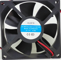
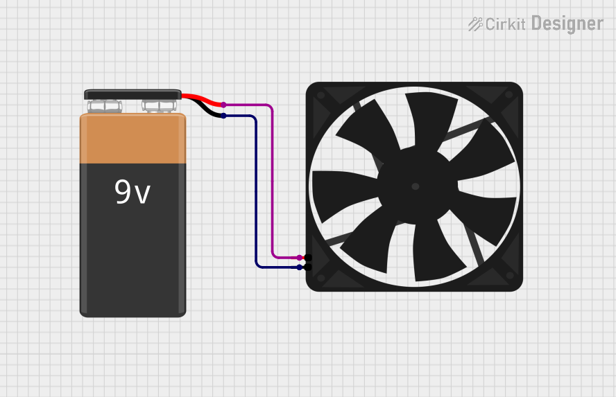
The FAN 12 V, manufactured by Arduino, is an electromechanical device designed to create airflow for cooling or ventilation purposes. It is commonly used in electronic devices to dissipate heat generated by components such as processors, power supplies, and other heat-sensitive parts. By maintaining optimal operating temperatures, the FAN 12 V ensures the longevity and reliability of electronic systems.
Explore Projects Built with FAN
 Open Project in Cirkit Designer
 Open Project in Cirkit Designer
 Open Project in Cirkit Designer
 Open Project in Cirkit Designer
Explore Projects Built with FAN
Open Project in Cirkit DesignerOpen Project in Cirkit DesignerOpen Project in Cirkit DesignerOpen Project in Cirkit DesignerCommon Applications and Use Cases
- Cooling microcontrollers, processors, and power supplies in electronic circuits.
- Ventilation in enclosures or cases to prevent overheating.
- Heat dissipation in 3D printers, robotics, and industrial equipment.
- General-purpose airflow management in small-scale systems.
Technical Specifications
The following table outlines the key technical details of the FAN 12 V:
| Parameter | Specification |
|---|---|
| Manufacturer | Arduino |
| Part ID | FAN 12 V |
| Operating Voltage | 12 V DC |
| Operating Current | 0.15 A (typical) |
| Power Consumption | 1.8 W |
| Airflow | 25 CFM (Cubic Feet per Minute) |
| Noise Level | 25 dBA |
| Dimensions | 40 mm x 40 mm x 10 mm |
| Connector Type | 2-pin JST or bare wires |
| Bearing Type | Sleeve Bearing |
| Operating Temperature | -10°C to 70°C |
| Lifespan | 30,000 hours (typical) |
Pin Configuration and Descriptions
The FAN 12 V typically comes with a 2-pin connector or bare wires for easy integration into circuits. The pin configuration is as follows:
| Pin/Wire Color | Function | Description |
|---|---|---|
| Red | VCC (+12 V) | Connect to the positive terminal of a 12 V DC power supply. |
| Black | GND (Ground) | Connect to the ground terminal of the power supply. |
Usage Instructions
How to Use the FAN 12 V in a Circuit
- Power Supply: Ensure you have a stable 12 V DC power source capable of supplying at least 0.15 A of current.
- Connections:
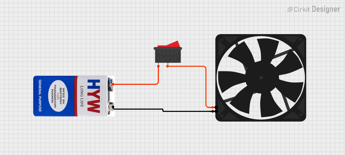
- Connect the red wire (VCC) to the positive terminal of the 12 V power supply.
- Connect the black wire (GND) to the ground terminal of the power supply.
- Mounting: Secure the fan in place using screws or adhesive mounts. Ensure the airflow direction aligns with your cooling requirements (airflow direction is typically indicated by an arrow on the fan housing).
- Optional Control: If you wish to control the fan speed, you can use a PWM (Pulse Width Modulation) signal from a microcontroller like the Arduino UNO.
Important Considerations and Best Practices
- Voltage Compatibility: Do not exceed the rated 12 V operating voltage to avoid damaging the fan.
- Airflow Direction: Verify the airflow direction to ensure proper cooling. The arrow on the fan housing indicates the airflow direction.
- Noise Management: If noise is a concern, consider using rubber mounts to reduce vibration.
- Dust and Maintenance: Periodically clean the fan blades to prevent dust buildup, which can reduce efficiency and increase noise.
- PWM Control: For variable speed control, use a transistor or MOSFET circuit to interface the fan with a PWM signal.
Example: Controlling the FAN 12 V with Arduino UNO
Below is an example of how to control the FAN 12 V using an Arduino UNO and a PWM signal:
// Define the pin connected to the fan's control circuit
const int fanPin = 9; // PWM pin on Arduino UNO

void setup() {
  pinMode(fanPin, OUTPUT); // Set the fan pin as an output
}

void loop() {
  // Set fan speed to 50% using PWM (128 out of 255)
  analogWrite(fanPin, 128); // 50% duty cycle for medium speed
  delay(5000); // Run the fan at this speed for 5 seconds

  // Set fan speed to 100% (maximum speed)
  analogWrite(fanPin, 255); // 100% duty cycle for full speed
  delay(5000); // Run the fan at full speed for 5 seconds

  // Turn off the fan
  analogWrite(fanPin, 0); // 0% duty cycle to stop the fan
  delay(5000); // Fan remains off for 5 seconds
}
Troubleshooting and FAQs
Common Issues and Solutions
Fan Does Not Spin:
- Cause: Incorrect wiring or insufficient power supply.
- Solution: Verify that the red wire is connected to +12 V and the black wire to GND. Ensure the power supply provides at least 0.15 A.
Fan Spins Slowly:
- Cause: Insufficient voltage or excessive load on the power supply.
- Solution: Check the voltage at the fan terminals using a multimeter. Ensure the power supply is not overloaded.
Excessive Noise:
- Cause: Dust buildup or improper mounting.
- Solution: Clean the fan blades and ensure the fan is securely mounted with vibration-dampening materials.
Fan Overheats:
- Cause: Prolonged operation in high-temperature environments.
- Solution: Ensure the operating temperature does not exceed 70°C. Improve ventilation around the fan.
FAQs
Q1: Can I use the FAN 12 V with a 5 V power supply?
A1: No, the FAN 12 V requires a 12 V DC power supply for proper operation. Using a lower voltage will result in insufficient airflow or failure to spin.
Q2: How do I reverse the airflow direction?
A2: The airflow direction is fixed and cannot be reversed. To change the airflow direction, physically rotate the fan or install it in the opposite orientation.
Q3: Can I control the fan speed without a microcontroller?
A3: Yes, you can use a variable resistor (potentiometer) or a dedicated fan speed controller circuit to adjust the voltage or PWM signal.
Q4: What is the lifespan of the FAN 12 V?
A4: The typical lifespan is 30,000 hours under normal operating conditions. Regular maintenance can help extend its life.