Cirkit Designer Logo
Cirkit Designer
Your all-in-one circuit design IDE
Home / 
Component Documentation

How to Use ZS-X11H v1: Examples, Pinouts, and Specs

Image of ZS-X11H v1
Cirkit Designer LogoDesign with ZS-X11H v1 in Cirkit Designer

Introduction

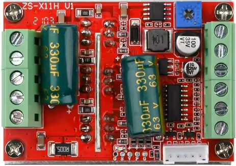
The ZS-X11H v1 is a versatile microcontroller module designed for a wide range of electronic projects. It features multiple input/output (I/O) pins, support for various communication protocols, and a compact form factor, making it ideal for integration into small devices. This module is well-suited for applications such as home automation, IoT devices, robotics, and other embedded systems requiring reliable and efficient control.

Common applications and use cases:

  • IoT devices and smart home systems
  • Robotics and automation projects
  • Sensor data acquisition and processing
  • Communication hubs for wireless or wired networks
  • Prototyping and educational projects

Explore Projects Built with ZS-X11H v1

Use Cirkit Designer to design, explore, and prototype these projects online. Some projects support real-time simulation. Click "Open Project" to start designing instantly!
Arduino Nano-Based Remote-Controlled Dual Motor System with LiPo Battery
Image of nano shield zkbm1: A project utilizing ZS-X11H v1 in a practical application
This circuit is designed to control two GM25 DC motors using a ZK-BM1 10A motor driver, which is managed by a NANO Shield Board. The NANO Shield Board receives input signals from an R6FG receiver and is powered by an 11.1V LiPo battery.
Cirkit Designer LogoOpen Project in Cirkit Designer
Satellite-Based Timing and Navigation System with SDR and Atomic Clock Synchronization
Image of GPS 시스템 측정 구성도_Confirm: A project utilizing ZS-X11H v1 in a practical application
This circuit appears to be a complex system involving power supply management, GPS and timing synchronization, and data communication. It includes a SI-TEX G1 Satellite Compass for GPS data, an XHTF1021 Atomic Rubidium Clock for precise timing, and Ettus USRP B200 units for software-defined radio communication. Power is supplied through various SMPS units and distributed via terminal blocks and DC jacks. Data communication is facilitated by Beelink MINI S12 N95 computers, RS232 splitters, and a 1000BASE-T Media Converter for network connectivity. RF Directional Couplers are used to interface antennas with the USRP units, and the entire system is likely contained within cases for protection and organization.
Cirkit Designer LogoOpen Project in Cirkit Designer
ESP32C3-Based Smart AC Light Controller with Voltage Sensing
Image of plugins: A project utilizing ZS-X11H v1 in a practical application
This circuit appears to be a smart AC power control system. The XIAO ESP32C3 microcontroller is used to monitor AC voltage through the ZMPT101B module and to control a 12v Relay, which in turn switches an AC Bulb on or off. The Mini AC-DC module provides the 5V power required by the microcontroller and the relay, while the AC Wire provides the AC power to the system.
Cirkit Designer LogoOpen Project in Cirkit Designer
ESP32-Based Smart Energy Monitoring and Control System
Image of SMART SOCKET: A project utilizing ZS-X11H v1 in a practical application
This circuit is designed to monitor AC voltage and current using ZMPT101B and ZMCT103C sensors, respectively, with an ESP32 microcontroller processing the sensor outputs. The XL4015 step-down module regulates the power supply to provide a stable voltage to the sensors, the ESP32, and an LCD I2C display. The ESP32 controls a 4-channel relay module for switching AC loads, and the system's operation can be interacted with via the LCD display and a push switch.
Cirkit Designer LogoOpen Project in Cirkit Designer

Explore Projects Built with ZS-X11H v1

Use Cirkit Designer to design, explore, and prototype these projects online. Some projects support real-time simulation. Click "Open Project" to start designing instantly!
Image of nano shield zkbm1: A project utilizing ZS-X11H v1 in a practical application
Arduino Nano-Based Remote-Controlled Dual Motor System with LiPo Battery
This circuit is designed to control two GM25 DC motors using a ZK-BM1 10A motor driver, which is managed by a NANO Shield Board. The NANO Shield Board receives input signals from an R6FG receiver and is powered by an 11.1V LiPo battery.
Cirkit Designer LogoOpen Project in Cirkit Designer
Image of GPS 시스템 측정 구성도_Confirm: A project utilizing ZS-X11H v1 in a practical application
Satellite-Based Timing and Navigation System with SDR and Atomic Clock Synchronization
This circuit appears to be a complex system involving power supply management, GPS and timing synchronization, and data communication. It includes a SI-TEX G1 Satellite Compass for GPS data, an XHTF1021 Atomic Rubidium Clock for precise timing, and Ettus USRP B200 units for software-defined radio communication. Power is supplied through various SMPS units and distributed via terminal blocks and DC jacks. Data communication is facilitated by Beelink MINI S12 N95 computers, RS232 splitters, and a 1000BASE-T Media Converter for network connectivity. RF Directional Couplers are used to interface antennas with the USRP units, and the entire system is likely contained within cases for protection and organization.
Cirkit Designer LogoOpen Project in Cirkit Designer
Image of plugins: A project utilizing ZS-X11H v1 in a practical application
ESP32C3-Based Smart AC Light Controller with Voltage Sensing
This circuit appears to be a smart AC power control system. The XIAO ESP32C3 microcontroller is used to monitor AC voltage through the ZMPT101B module and to control a 12v Relay, which in turn switches an AC Bulb on or off. The Mini AC-DC module provides the 5V power required by the microcontroller and the relay, while the AC Wire provides the AC power to the system.
Cirkit Designer LogoOpen Project in Cirkit Designer
Image of SMART SOCKET: A project utilizing ZS-X11H v1 in a practical application
ESP32-Based Smart Energy Monitoring and Control System
This circuit is designed to monitor AC voltage and current using ZMPT101B and ZMCT103C sensors, respectively, with an ESP32 microcontroller processing the sensor outputs. The XL4015 step-down module regulates the power supply to provide a stable voltage to the sensors, the ESP32, and an LCD I2C display. The ESP32 controls a 4-channel relay module for switching AC loads, and the system's operation can be interacted with via the LCD display and a push switch.
Cirkit Designer LogoOpen Project in Cirkit Designer

Technical Specifications

The ZS-X11H v1 offers the following key technical details:

Parameter Specification
Operating Voltage 3.3V to 5V
Input Voltage Range 3.3V to 12V
Digital I/O Pins 14
Analog Input Pins 6
Communication Protocols UART, I2C, SPI
Clock Speed 16 MHz
Flash Memory 32 KB
SRAM 2 KB
EEPROM 1 KB
Dimensions 35mm x 25mm x 5mm

Pin Configuration and Descriptions

The ZS-X11H v1 has a total of 20 pins, including power, ground, and I/O pins. Below is the pin configuration:

Pin Number Label Description
1 VIN Input voltage (3.3V to 12V)
2 GND Ground
3 3V3 3.3V output for powering external components
4 RESET Reset pin (active low)
5-12 D0-D7 Digital I/O pins
13 TX UART Transmit (TX)
14 RX UART Receive (RX)
15-16 A0-A1 Analog input pins
17-18 SCL, SDA I2C Clock (SCL) and Data (SDA) lines
19 MOSI SPI Master Out Slave In
20 MISO SPI Master In Slave Out

Usage Instructions

How to Use the ZS-X11H v1 in a Circuit

  1. Powering the Module: Connect the VIN pin to a power source (3.3V to 12V) and the GND pin to ground. Alternatively, you can power the module using the 3V3 pin if your power source provides a regulated 3.3V.
  2. Connecting I/O Pins: Use the digital (D0-D7) and analog (A0-A1) pins to interface with sensors, actuators, or other peripherals.
  3. Communication: Utilize the UART, I2C, or SPI pins for communication with other devices or microcontrollers.
  4. Programming: The ZS-X11H v1 can be programmed using a compatible IDE (e.g., Arduino IDE) via the UART pins (TX and RX).

Important Considerations and Best Practices

  • Ensure the input voltage does not exceed the specified range (3.3V to 12V) to avoid damaging the module.
  • Use pull-up resistors on the I2C lines (SCL and SDA) if required by your application.
  • Avoid connecting high-current loads directly to the I/O pins; use external transistors or relays for such applications.
  • For stable operation, decouple the power supply with a 0.1µF capacitor close to the VIN pin.

Example: Connecting to an Arduino UNO

The ZS-X11H v1 can be connected to an Arduino UNO for extended functionality. Below is an example of interfacing the module via UART:

Arduino Code Example

// Example: Communicating with ZS-X11H v1 via UART
// This code sends a message to the ZS-X11H v1 and reads its response.

void setup() {
  Serial.begin(9600); // Initialize Arduino's UART at 9600 baud
  delay(1000);        // Wait for the ZS-X11H v1 to initialize
  Serial.println("Hello ZS-X11H!"); // Send a message to the module
}

void loop() {
  if (Serial.available() > 0) { // Check if data is received from ZS-X11H
    String response = Serial.readString(); // Read the response
    Serial.println("ZS-X11H says: " + response); // Print the response
  }
}

Troubleshooting and FAQs

Common Issues and Solutions

  1. Module Not Powering On

    • Cause: Incorrect input voltage or loose connections.
    • Solution: Verify that the VIN pin is receiving 3.3V to 12V and that all connections are secure.
  2. No Communication via UART

    • Cause: Incorrect baud rate or wiring.
    • Solution: Ensure the baud rate in your code matches the module's default (e.g., 9600). Check the TX and RX connections.
  3. I2C Devices Not Responding

    • Cause: Missing pull-up resistors or incorrect wiring.
    • Solution: Add 4.7kΩ pull-up resistors to the SCL and SDA lines. Verify the wiring.
  4. Analog Readings Are Inaccurate

    • Cause: Noise or incorrect reference voltage.
    • Solution: Use a decoupling capacitor near the analog input pins and ensure a stable reference voltage.

FAQs

  • Q: Can the ZS-X11H v1 operate at 5V logic levels?
    A: Yes, the module supports both 3.3V and 5V logic levels.

  • Q: Is the ZS-X11H v1 compatible with Arduino libraries?
    A: Yes, it can be programmed using the Arduino IDE and is compatible with most Arduino libraries.

  • Q: What is the maximum current output of the I/O pins?
    A: Each I/O pin can source or sink up to 20mA. For higher currents, use external drivers.

  • Q: Can I use the ZS-X11H v1 for wireless communication?
    A: The module itself does not have wireless capabilities, but you can connect external wireless modules (e.g., ESP8266) via UART or SPI.

This concludes the documentation for the ZS-X11H v1. For further assistance, refer to the manufacturer's datasheet or support resources.