
How to Use Adafruit Gear-Reduced Stepper Motor (small): Examples, Pinouts, and Specs
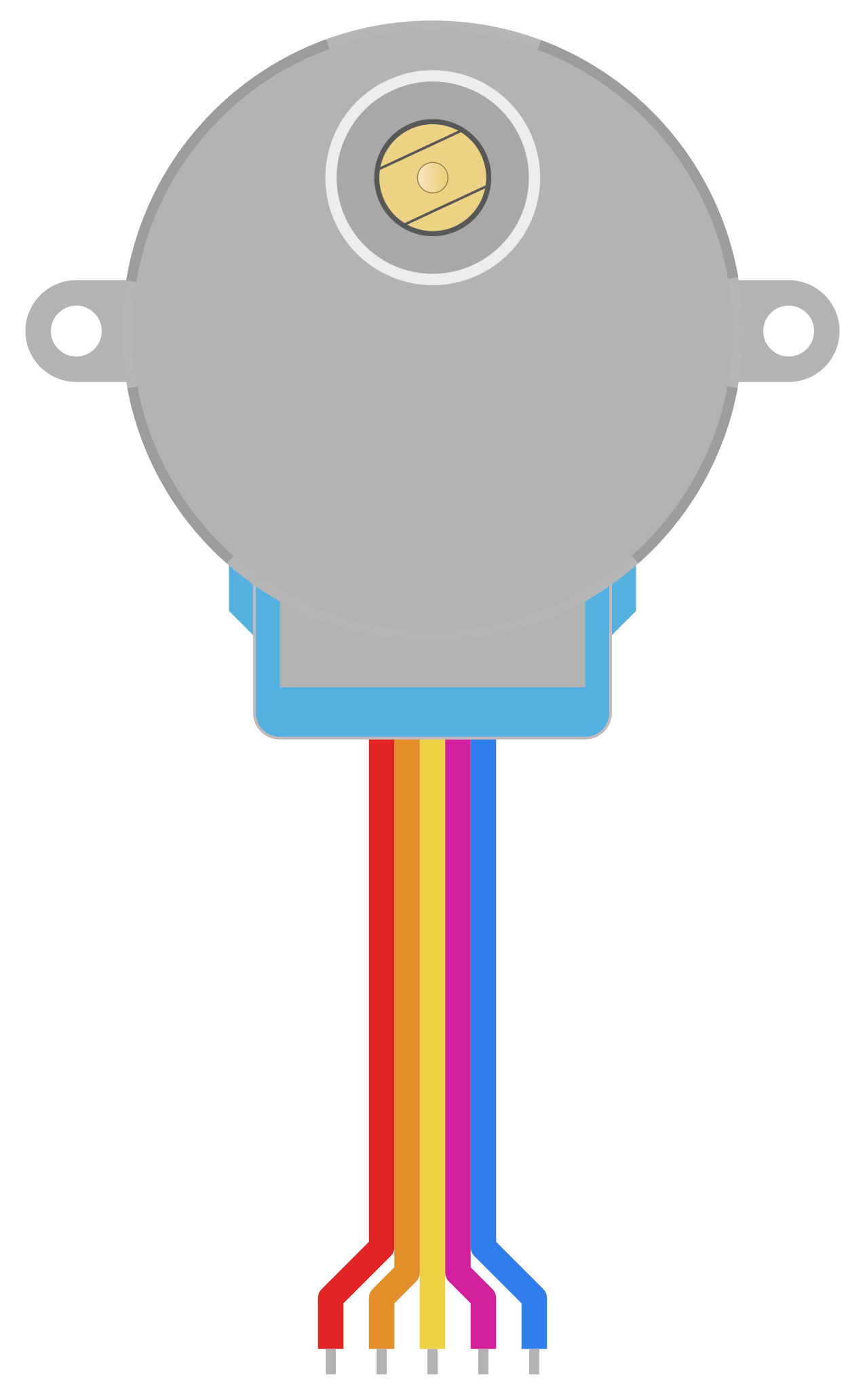
 Design with Adafruit Gear-Reduced Stepper Motor (small) in Cirkit Designer
Introduction
The Adafruit Gear-Reduced Stepper Motor (Small) is a compact and versatile stepper motor designed for applications requiring precise control of rotation. Its built-in gear reduction mechanism increases torque while reducing speed, making it ideal for projects where controlled, high-torque motion is essential. This motor is particularly well-suited for robotics, automation, 3D printing, and CNC applications.
Common applications include:
- Robotics (e.g., robotic arms, grippers)
- Automated systems (e.g., conveyor belts, camera sliders)
- Precision control mechanisms (e.g., 3D printers, CNC machines)
- Educational and prototyping projects
Explore Projects Built with Adafruit Gear-Reduced Stepper Motor (small)
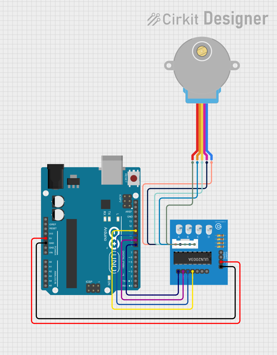 Open Project in Cirkit Designer
 Open Project in Cirkit Designer
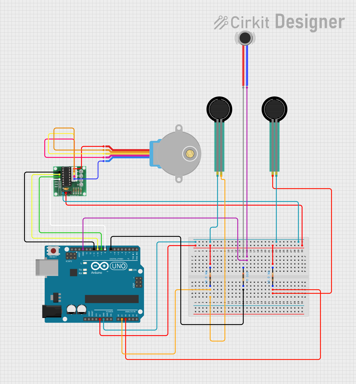 Open Project in Cirkit Designer
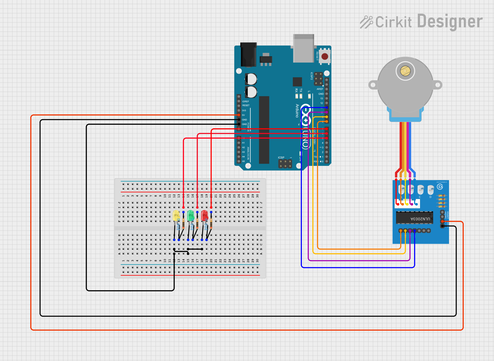 Open Project in Cirkit Designer
Explore Projects Built with Adafruit Gear-Reduced Stepper Motor (small)
Open Project in Cirkit DesignerOpen Project in Cirkit DesignerOpen Project in Cirkit DesignerOpen Project in Cirkit DesignerTechnical Specifications
Below are the key technical details of the Adafruit Gear-Reduced Stepper Motor (Small):
| Parameter | Value |
|---|---|
| Motor Type | Bipolar Stepper Motor |
| Step Angle (without gear reduction) | 7.5° per step |
| Gear Reduction Ratio | 1:64 |
| Effective Step Angle | ~0.117° per step (with gears) |
| Rated Voltage | 5V DC |
| Rated Current | 190 mA per phase |
| Torque (with gear reduction) | ~1.5 kg·cm |
| Shaft Diameter | 3 mm |
| Dimensions | 28 mm x 28 mm x 20 mm |
| Weight | ~30 g |
Pin Configuration and Descriptions
The motor has four wires for its bipolar configuration. These wires correspond to the two motor windings.
| Wire Color | Function | Description |
|---|---|---|
| Red | Coil A (positive) | Connect to one side of winding A |
| Blue | Coil A (negative) | Connect to the other side of winding A |
| Green | Coil B (positive) | Connect to one side of winding B |
| Black | Coil B (negative) | Connect to the other side of winding B |
Note: Ensure proper connection to a stepper motor driver to avoid damage.
Usage Instructions
How to Use the Component in a Circuit
Connect to a Stepper Motor Driver:
- Use a compatible stepper motor driver (e.g., Adafruit Motor Shield or A4988 driver).
- Connect the motor wires to the driver as per the pin configuration table.
- Ensure the driver is powered with the appropriate voltage (typically 5V or higher).
Power Supply:
- Use a regulated 5V DC power supply for the motor.
- Ensure the power supply can provide sufficient current (at least 200 mA).
Control Signals:
- Use a microcontroller (e.g., Arduino UNO) to send step and direction signals to the motor driver.
- Configure the microcontroller to generate the required pulse sequence for precise control.
Important Considerations and Best Practices
- Current Limiting: Set the current limit on the motor driver to prevent overheating or damage to the motor.
- Step Resolution: Use microstepping (if supported by the driver) for smoother motion and higher precision.
- Avoid Stalling: Do not exceed the motor's torque limit to avoid stalling or losing steps.
- Secure Mounting: Mount the motor securely to prevent vibrations or misalignment during operation.
Example Code for Arduino UNO
Below is an example of how to control the Adafruit Gear-Reduced Stepper Motor using an Arduino UNO and an A4988 stepper motor driver:
// Include the Stepper library for controlling stepper motors
#include <Stepper.h>

// Define the number of steps per revolution for the motor
// With a 1:64 gear reduction, the effective steps per revolution is 2048
#define STEPS_PER_REV 2048

// Initialize the Stepper object with steps per revolution and motor pins
Stepper myStepper(STEPS_PER_REV, 8, 9, 10, 11);
// Pins 8, 9, 10, 11 are connected to the motor driver

void setup() {
  // Set the motor speed (in RPM)
  myStepper.setSpeed(10); // 10 RPM for slow, precise movement

  // Initialize serial communication for debugging
  Serial.begin(9600);
  Serial.println("Stepper Motor Test");
}

void loop() {
  // Rotate the motor 1 full revolution clockwise
  Serial.println("Rotating clockwise...");
  myStepper.step(STEPS_PER_REV);

  delay(1000); // Wait for 1 second

  // Rotate the motor 1 full revolution counterclockwise
  Serial.println("Rotating counterclockwise...");
  myStepper.step(-STEPS_PER_REV);

  delay(1000); // Wait for 1 second
}
Explanation of the Code:
- The
Stepperlibrary simplifies stepper motor control. - The
STEPS_PER_REVconstant accounts for the gear reduction, ensuring precise control. - The
setSpeed()function sets the motor speed in revolutions per minute (RPM). - The
step()function moves the motor by a specified number of steps (positive for clockwise, negative for counterclockwise).
Troubleshooting and FAQs
Common Issues and Solutions
Motor Not Moving:
- Cause: Incorrect wiring or loose connections.
- Solution: Double-check the wiring and ensure all connections are secure.
Motor Vibrates but Does Not Rotate:
- Cause: Incorrect step sequence or insufficient current.
- Solution: Verify the step sequence and adjust the current limit on the driver.
Overheating:
- Cause: Excessive current or prolonged operation at high torque.
- Solution: Reduce the current limit and allow the motor to cool periodically.
Skipping Steps:
- Cause: Exceeding the torque limit or incorrect microstepping settings.
- Solution: Reduce the load on the motor or enable microstepping.
FAQs
Q: Can I power the motor directly from the Arduino UNO?
A: No, the Arduino UNO cannot supply sufficient current for the motor. Use an external power supply and a motor driver.
Q: What is the advantage of the gear reduction mechanism?
A: The gear reduction increases torque and precision, making the motor suitable for applications requiring fine control and high torque.
Q: Can I use this motor for continuous rotation?
A: Yes, but stepper motors are designed for precise positioning rather than high-speed continuous rotation. For continuous rotation at high speeds, consider using a DC motor.
Q: How do I determine the correct current limit for my driver?
A: Refer to the motor's rated current (190 mA per phase) and set the driver’s current limit accordingly to avoid overheating or damage.
This concludes the documentation for the Adafruit Gear-Reduced Stepper Motor (Small).