How to Use TCRT: Examples, Pinouts, and Specs
Introduction
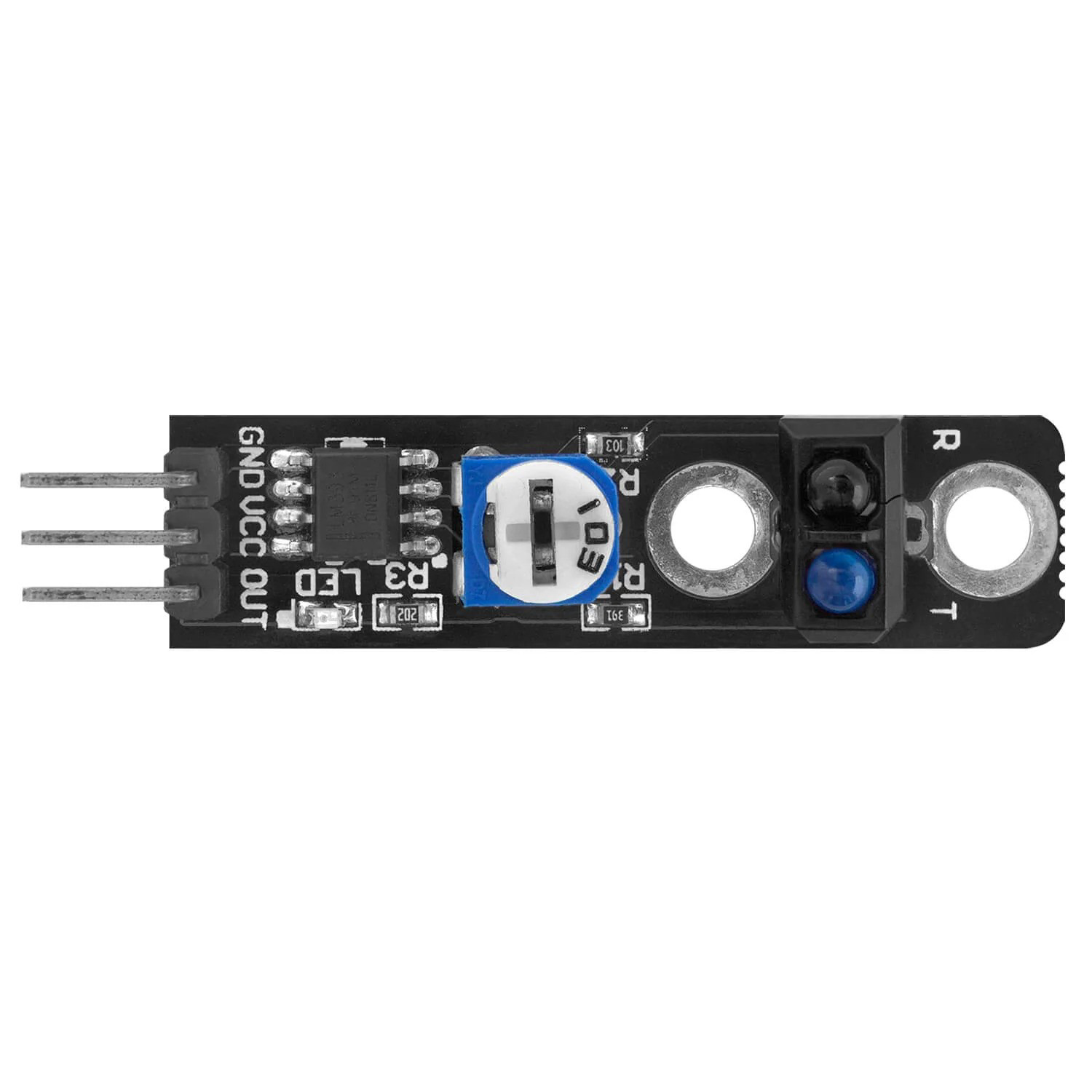
The TCRT reflective optical sensor is a versatile component that combines an infrared emitter and a phototransistor in a single package. This sensor is commonly used for proximity sensing and object detection. It is widely utilized in applications such as line-following robots, optical encoders, and non-contact switching.
Explore Projects Built with TCRT
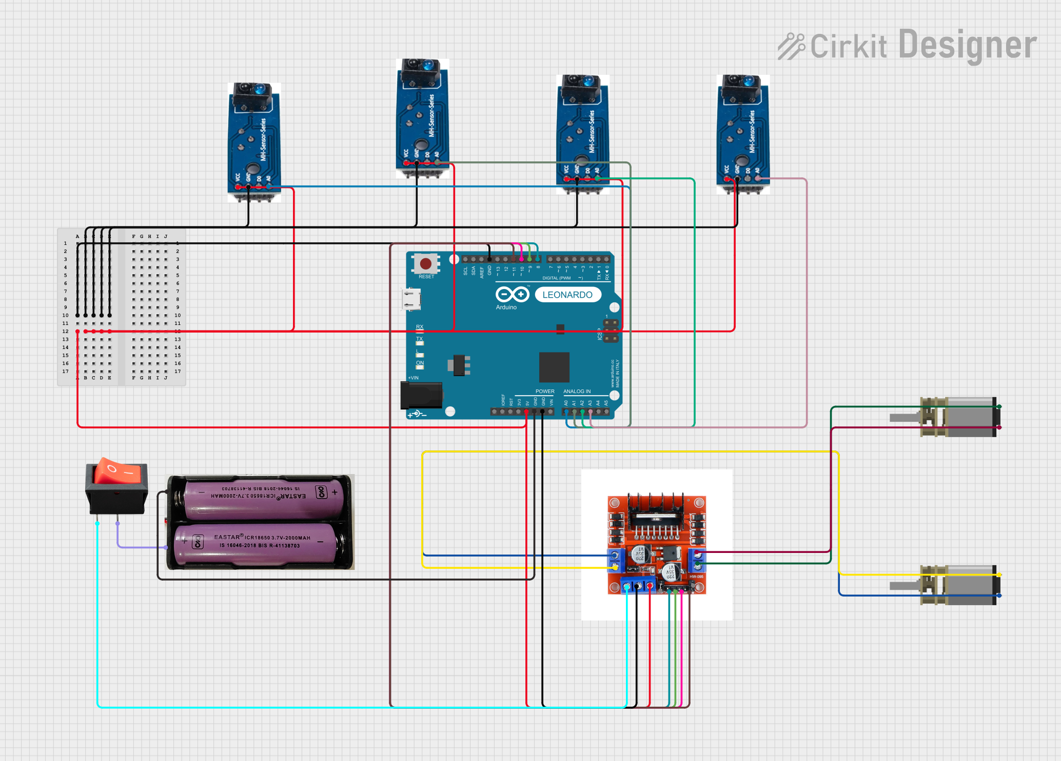
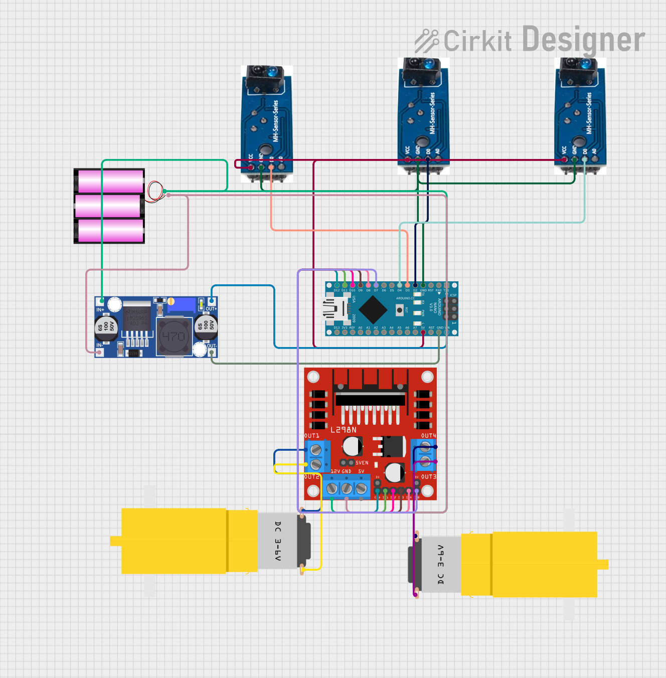
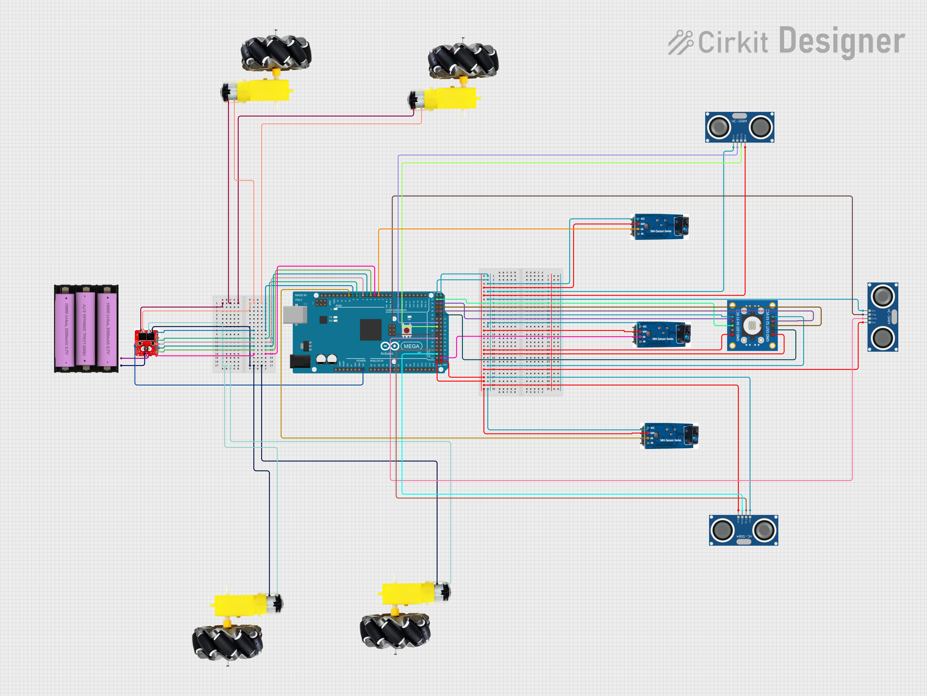
Explore Projects Built with TCRT
Technical Specifications
Key Technical Details
| Parameter | Value |
|---|---|
| Operating Voltage | 4.5V to 5.5V |
| Forward Current (IF) | 60 mA |
| Collector Current | 100 mA |
| Collector-Emitter Voltage (VCEO) | 32V |
| Emitter-Collector Voltage (VECO) | 5V |
| Operating Temperature | -25°C to +85°C |
| Peak Wavelength | 950 nm |
| Detection Range | 0.2 mm to 15 mm |
Pin Configuration and Descriptions
| Pin Number | Pin Name | Description |
|---|---|---|
| 1 | Emitter | Connect to the positive terminal of the power supply (typically 5V) |
| 2 | Collector | Connect to the input pin of the microcontroller or the load |
| 3 | Ground | Connect to the ground of the power supply |
| 4 | Anode | Connect to the positive terminal of the power supply (typically 5V) |
| 5 | Cathode | Connect to the ground through a current-limiting resistor |
Usage Instructions
How to Use the Component in a Circuit
Power Supply:
- Connect the Anode (Pin 4) to the positive terminal of the power supply (typically 5V).
- Connect the Cathode (Pin 5) to the ground through a current-limiting resistor (typically 220Ω).
Emitter and Collector:
- Connect the Emitter (Pin 1) to the positive terminal of the power supply (typically 5V).
- Connect the Collector (Pin 2) to the input pin of the microcontroller or the load.
Ground:
- Connect the Ground (Pin 3) to the ground of the power supply.
Important Considerations and Best Practices
- Current Limiting Resistor: Always use a current-limiting resistor with the infrared emitter to prevent damage due to excessive current.
- Distance Calibration: Adjust the distance between the sensor and the object for optimal performance. The detection range is typically between 0.2 mm to 15 mm.
- Ambient Light: Be aware of ambient light interference. The sensor may give false readings in the presence of strong ambient light.
Example Code for Arduino UNO
/*
  TCRT Reflective Optical Sensor Example
  This code demonstrates how to use the TCRT sensor with an Arduino UNO.
  The sensor detects the presence of an object and turns on an LED.
*/

const int sensorPin = 2; // Pin connected to the collector of the phototransistor
const int ledPin = 13;   // Pin connected to the LED

void setup() {
  pinMode(sensorPin, INPUT); // Set sensor pin as input
  pinMode(ledPin, OUTPUT);   // Set LED pin as output
  Serial.begin(9600);        // Initialize serial communication
}

void loop() {
  int sensorValue = digitalRead(sensorPin); // Read the sensor value

  if (sensorValue == LOW) {
    // Object detected
    digitalWrite(ledPin, HIGH); // Turn on the LED
    Serial.println("Object detected");
  } else {
    // No object detected
    digitalWrite(ledPin, LOW);  // Turn off the LED
    Serial.println("No object detected");
  }

  delay(100); // Small delay for stability
}
Troubleshooting and FAQs
Common Issues Users Might Face
No Detection:
- Solution: Ensure the sensor is properly connected and the current-limiting resistor is in place. Check the distance between the sensor and the object.
False Readings:
- Solution: Reduce ambient light interference by shielding the sensor or using it in a controlled environment.
Intermittent Detection:
- Solution: Check for loose connections and ensure the power supply is stable.
FAQs
Q1: Can the TCRT sensor detect transparent objects?
- A1: The TCRT sensor may have difficulty detecting transparent objects due to the low reflectivity of infrared light.
Q2: What is the maximum detection range of the TCRT sensor?
- A2: The maximum detection range is typically 15 mm, but it can vary based on the reflectivity of the object and ambient conditions.
Q3: Can I use the TCRT sensor with a 3.3V power supply?
- A3: The TCRT sensor is designed to operate at 4.5V to 5.5V. Using a 3.3V power supply may result in reduced performance or failure to operate.
By following this documentation, users can effectively integrate the TCRT reflective optical sensor into their projects, ensuring reliable proximity sensing and object detection.