How to Use tdr: Examples, Pinouts, and Specs
Introduction
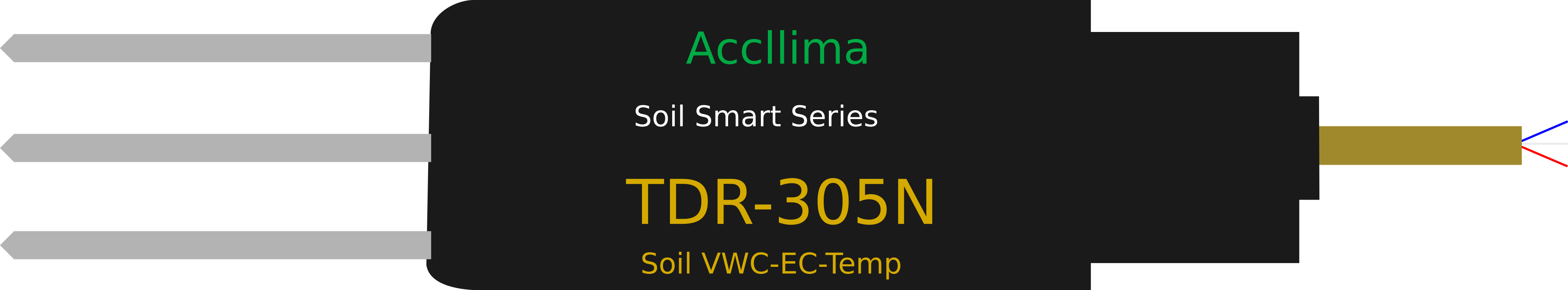
A Time Domain Reflectometer (TDR) is a diagnostic tool used to analyze the characteristics of electrical transmission lines. It works by sending a short electrical pulse down a cable and measuring the reflected signals to detect faults, impedance mismatches, or changes in the cable's properties. TDRs are widely used in industries such as telecommunications, aerospace, and electrical engineering for cable testing, fault location, and quality assurance.
Explore Projects Built with tdr
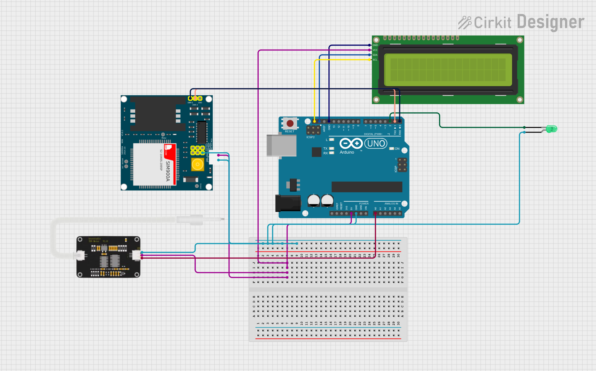

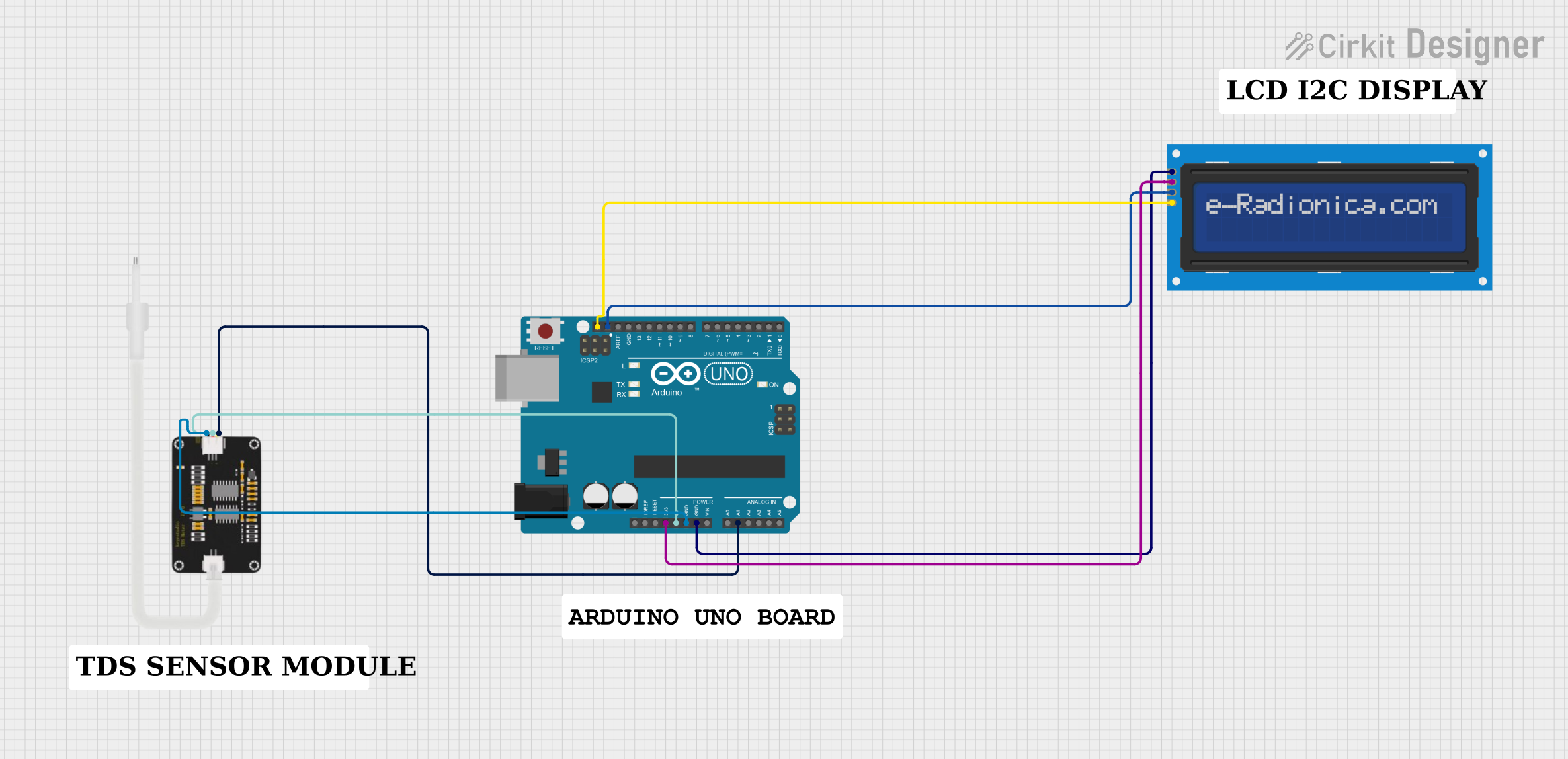
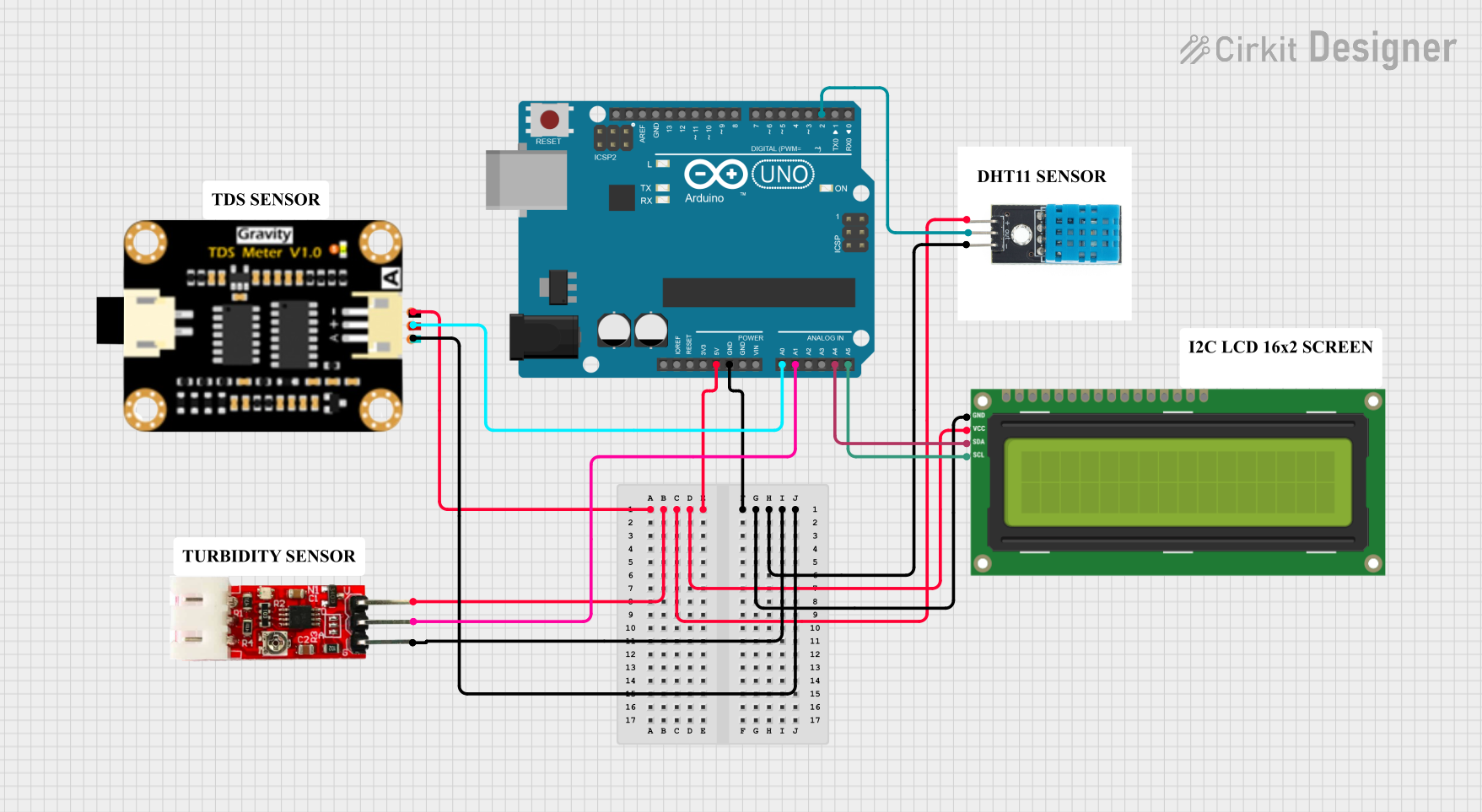
Explore Projects Built with tdr
Common Applications and Use Cases
- Identifying and locating faults in coaxial cables, twisted pairs, or other transmission lines.
- Measuring cable lengths and determining the location of breaks or shorts.
- Detecting impedance mismatches or discontinuities in transmission lines.
- Verifying the integrity of installed cables in telecommunications and networking.
- Testing and maintaining radar systems, antennas, and other RF equipment.
Technical Specifications
Below are the general technical specifications for a typical TDR device. Note that specific models may vary in their capabilities.
Key Technical Details
| Parameter | Specification |
|---|---|
| Pulse Rise Time | 100 ps to 10 ns (model-dependent) |
| Measurement Range | Up to 20 km (depending on cable type) |
| Impedance Range | 1 Ω to 10 kΩ |
| Resolution | 0.1 m to 1 m |
| Output Pulse Amplitude | 1 V to 10 V |
| Power Supply | 9V battery or external DC (5V-12V) |
| Display | LCD or graphical interface |
| Connector Type | BNC, SMA, or other RF connectors |
Pin Configuration and Descriptions
For TDR devices with external interfaces, the pin configuration of the input/output connectors is as follows:
Example: BNC Connector Pinout
| Pin Name | Description |
|---|---|
| Signal (Center) | Transmits the pulse and receives the reflection. |
| Ground (Outer) | Provides the ground reference for the signal. |
Example: Power Input Connector (DC Barrel Jack)
| Pin Name | Description |
|---|---|
| Positive (+) | Connects to the positive terminal of the power supply. |
| Negative (-) | Connects to the ground terminal of the power supply. |
Usage Instructions
How to Use the TDR in a Circuit
Connect the TDR to the Cable Under Test (CUT):
- Attach the TDR's signal output to one end of the cable using the appropriate connector (e.g., BNC or SMA).
- Ensure the other end of the cable is either open or terminated with a known impedance.
Power On the TDR:
- Supply power to the TDR using a 9V battery or an external DC power source within the specified voltage range.
Configure the TDR Settings:
- Set the impedance range, pulse amplitude, and measurement range based on the cable type and expected fault location.
Initiate the Test:
- Trigger the TDR to send a pulse down the cable. The device will display the reflected signal on its screen.
Analyze the Results:
- Use the displayed waveform to identify faults, impedance mismatches, or cable breaks. The time delay of the reflection corresponds to the distance to the fault.
Important Considerations and Best Practices
- Cable Type: Ensure the TDR is compatible with the type of cable being tested (e.g., coaxial, twisted pair).
- Impedance Matching: Use proper termination to avoid additional reflections that may interfere with measurements.
- Environmental Factors: Avoid testing in environments with high electrical noise, as it may affect the accuracy of the results.
- Calibration: Periodically calibrate the TDR to maintain measurement accuracy.
- Safety: Disconnect the cable from any active power source before testing to prevent damage to the TDR or injury.
Example: Using a TDR with an Arduino UNO
While TDRs are standalone devices, you can interface them with an Arduino UNO for automated testing or data logging. Below is an example of how to trigger a TDR and read its output using an Arduino:
// Example: Interfacing a TDR with Arduino UNO
// This code triggers the TDR and reads the reflected signal via an analog pin.

const int tdrTriggerPin = 7;  // Digital pin to trigger the TDR
const int tdrOutputPin = A0;  // Analog pin to read the TDR output

void setup() {
  pinMode(tdrTriggerPin, OUTPUT);  // Set trigger pin as output
  pinMode(tdrOutputPin, INPUT);    // Set output pin as input
  Serial.begin(9600);             // Initialize serial communication
}

void loop() {
  // Trigger the TDR by sending a pulse
  digitalWrite(tdrTriggerPin, HIGH);  // Send HIGH signal to trigger
  delayMicroseconds(10);              // Keep the pulse duration short
  digitalWrite(tdrTriggerPin, LOW);   // End the trigger pulse

  // Read the reflected signal from the TDR
  int reflectedSignal = analogRead(tdrOutputPin);

  // Print the reflected signal value to the Serial Monitor
  Serial.print("Reflected Signal: ");
  Serial.println(reflectedSignal);

  delay(1000);  // Wait 1 second before the next measurement
}
Troubleshooting and FAQs
Common Issues and Solutions
| Issue | Solution |
|---|---|
| No signal displayed on the TDR. | Check the power supply and ensure the cable is properly connected. |
| Reflections are unclear or noisy. | Verify impedance matching and test in a low-noise environment. |
| Incorrect fault location. | Ensure the correct velocity factor is set for the cable under test. |
| TDR does not power on. | Check the battery or external power source for proper voltage levels. |
FAQs
Can I use a TDR to test live cables?
- No, always disconnect the cable from any active power source before testing to avoid damage to the TDR or injury.
What is the velocity factor, and why is it important?
- The velocity factor is the speed at which a signal travels through a cable relative to the speed of light. It is crucial for accurately calculating the distance to a fault.
How do I interpret the TDR waveform?
- Peaks or dips in the waveform indicate impedance changes, such as faults, connectors, or cable ends. The time delay of these features corresponds to their distance from the TDR.
Can I use a TDR for fiber optic cables?
- No, TDRs are designed for electrical cables. For fiber optics, use an Optical Time Domain Reflectometer (OTDR).
By following this documentation, users can effectively operate a TDR, troubleshoot issues, and interpret results for a wide range of applications.