Cirkit Designer Logo
Cirkit Designer
Your all-in-one circuit design IDE
Home / 
Component Documentation

How to Use Hi-12F-Kit: Examples, Pinouts, and Specs

Image of Hi-12F-Kit
Cirkit Designer LogoDesign with Hi-12F-Kit in Cirkit Designer

Introduction

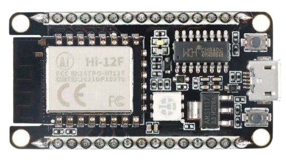
The Hi-12F-Kit, manufactured by Hisilicon, is a versatile electronic development kit designed for prototyping and testing various circuits. It includes a wide range of components such as resistors, capacitors, connectors, and other essential parts, making it an ideal choice for hobbyists, students, and professionals. The kit is designed to simplify the process of creating and experimenting with electronic designs, offering flexibility and ease of use.

Explore Projects Built with Hi-12F-Kit

Use Cirkit Designer to design, explore, and prototype these projects online. Some projects support real-time simulation. Click "Open Project" to start designing instantly!
Battery-Powered Sumo Robot with IR Sensors and DC Motors
Image of MASSIVE SUMO AUTO BOARD: A project utilizing Hi-12F-Kit in a practical application
This circuit is designed for a robotic system, featuring a Massive Sumo Board as the central controller. It integrates multiple FS-80NK diffuse IR sensors and IR line sensors for obstacle detection and line following, respectively, and controls two GM25 DC motors via MD13s motor drivers for movement. Power is supplied by an 11.1V LiPo battery.
Cirkit Designer LogoOpen Project in Cirkit Designer
Battery-Powered Emergency Alert System with NUCLEO-F072RB, SIM800L, and GPS NEO 6M
Image of women safety: A project utilizing Hi-12F-Kit in a practical application
This circuit is an emergency alert system that uses a NUCLEO-F072RB microcontroller to send SMS alerts and make calls via a SIM800L GSM module, while obtaining location data from a GPS NEO 6M module. The system is powered by a Li-ion battery and includes a TP4056 module for battery charging and protection, with a rocker switch to control power to the microcontroller.
Cirkit Designer LogoOpen Project in Cirkit Designer
ESP32-Based Environmental Monitoring and Alert System with Solar Charging
Image of mark: A project utilizing Hi-12F-Kit in a practical application
This circuit features an ESP32 Devkit V1 microcontroller connected to various sensors and modules for monitoring and communication purposes. It includes an MQ-2 gas sensor and a DHT11 temperature and humidity sensor, both interfaced with the ESP32 for environmental data collection. The circuit is powered by a 12V battery, regulated to 5V by step-down converters, and includes a solar charge controller connected to a solar panel for battery charging, a UPS module for power management, and a SIM900A module for GSM communication. Additionally, there is a WS2812 RGB LED strip for visual feedback and a piezo buzzer for audio alerts, both controlled by the ESP32.
Cirkit Designer LogoOpen Project in Cirkit Designer
ESP32-Based Environmental Monitoring and Alert System with Solar Charging
Image of Schematic: A project utilizing Hi-12F-Kit in a practical application
This circuit features an ESP32 Devkit V1 microcontroller connected to various sensors and devices, including a DHT11 temperature and humidity sensor, an MQ-2 gas sensor, and a WS2812 RGB LED strip. The ESP32 controls the LED strip and processes sensor readings, while a SIM900A module provides cellular communication capabilities. Power management is handled by a UPS module fed by a 12V battery charged via a solar panel and charge controller, with voltage regulation provided by step-down converters. Additionally, a piezo buzzer is included for audible alerts, and the system's safety is ensured by a circuit breaker connected to a switching power supply for AC to DC conversion.
Cirkit Designer LogoOpen Project in Cirkit Designer

Explore Projects Built with Hi-12F-Kit

Use Cirkit Designer to design, explore, and prototype these projects online. Some projects support real-time simulation. Click "Open Project" to start designing instantly!
Image of MASSIVE SUMO AUTO BOARD: A project utilizing Hi-12F-Kit in a practical application
Battery-Powered Sumo Robot with IR Sensors and DC Motors
This circuit is designed for a robotic system, featuring a Massive Sumo Board as the central controller. It integrates multiple FS-80NK diffuse IR sensors and IR line sensors for obstacle detection and line following, respectively, and controls two GM25 DC motors via MD13s motor drivers for movement. Power is supplied by an 11.1V LiPo battery.
Cirkit Designer LogoOpen Project in Cirkit Designer
Image of women safety: A project utilizing Hi-12F-Kit in a practical application
Battery-Powered Emergency Alert System with NUCLEO-F072RB, SIM800L, and GPS NEO 6M
This circuit is an emergency alert system that uses a NUCLEO-F072RB microcontroller to send SMS alerts and make calls via a SIM800L GSM module, while obtaining location data from a GPS NEO 6M module. The system is powered by a Li-ion battery and includes a TP4056 module for battery charging and protection, with a rocker switch to control power to the microcontroller.
Cirkit Designer LogoOpen Project in Cirkit Designer
Image of mark: A project utilizing Hi-12F-Kit in a practical application
ESP32-Based Environmental Monitoring and Alert System with Solar Charging
This circuit features an ESP32 Devkit V1 microcontroller connected to various sensors and modules for monitoring and communication purposes. It includes an MQ-2 gas sensor and a DHT11 temperature and humidity sensor, both interfaced with the ESP32 for environmental data collection. The circuit is powered by a 12V battery, regulated to 5V by step-down converters, and includes a solar charge controller connected to a solar panel for battery charging, a UPS module for power management, and a SIM900A module for GSM communication. Additionally, there is a WS2812 RGB LED strip for visual feedback and a piezo buzzer for audio alerts, both controlled by the ESP32.
Cirkit Designer LogoOpen Project in Cirkit Designer
Image of Schematic: A project utilizing Hi-12F-Kit in a practical application
ESP32-Based Environmental Monitoring and Alert System with Solar Charging
This circuit features an ESP32 Devkit V1 microcontroller connected to various sensors and devices, including a DHT11 temperature and humidity sensor, an MQ-2 gas sensor, and a WS2812 RGB LED strip. The ESP32 controls the LED strip and processes sensor readings, while a SIM900A module provides cellular communication capabilities. Power management is handled by a UPS module fed by a 12V battery charged via a solar panel and charge controller, with voltage regulation provided by step-down converters. Additionally, a piezo buzzer is included for audible alerts, and the system's safety is ensured by a circuit breaker connected to a switching power supply for AC to DC conversion.
Cirkit Designer LogoOpen Project in Cirkit Designer

Common Applications and Use Cases

  • Rapid prototyping of electronic circuits
  • Educational purposes for learning electronics
  • Testing and debugging circuit designs
  • Building small-scale IoT or embedded systems
  • Experimenting with Arduino, Raspberry Pi, or other microcontroller platforms

Technical Specifications

The Hi-12F-Kit includes a variety of components and tools to support a wide range of electronic projects. Below are the key technical details:

General Specifications

Parameter Value
Manufacturer Hisilicon
Part ID Hi-12F-Kit
Kit Type Electronic Development Kit
Supported Voltage Range 3.3V to 12V
Operating Temperature -20°C to 70°C
Included Components Resistors, capacitors, connectors, wires,
breadboard, LEDs, and more

Pin Configuration and Descriptions

The Hi-12F-Kit does not have a single pinout, as it is a collection of components. However, here is a breakdown of some key components included in the kit:

Resistors

Resistor Value (Ohms) Quantity Tolerance
220 10 ±5%
1k 10 ±5%
10k 10 ±5%

Capacitors

Capacitor Type Value (µF) Quantity
Ceramic 0.1 10
Electrolytic 10 5
Electrolytic 100 5

LEDs

LED Color Forward Voltage (V) Quantity
Red 2.0 5
Green 2.1 5
Blue 3.0 5

Connectors and Wires

Component Description Quantity
Jumper Wires Male-to-Male, Male-to-Female 20
Breadboard 400 tie-points 1
Pin Headers 40-pin breakable 2

Usage Instructions

The Hi-12F-Kit is designed to be user-friendly and compatible with a variety of platforms, including Arduino and Raspberry Pi. Follow these steps to use the kit effectively:

Step 1: Setting Up the Breadboard

  1. Place the breadboard on a flat surface.
  2. Connect the power supply to the breadboard's power rails (3.3V or 5V, depending on your circuit requirements).
  3. Use jumper wires to connect components as per your circuit design.

Step 2: Connecting Components

  1. Select the required resistors, capacitors, and other components from the kit.
  2. Insert the components into the breadboard, ensuring proper orientation for polarized components (e.g., electrolytic capacitors, LEDs).
  3. Use jumper wires to make connections between components.

Step 3: Testing the Circuit

  1. Double-check all connections to ensure they match your circuit diagram.
  2. Power on the circuit and observe its behavior.
  3. Use a multimeter or oscilloscope to measure voltages, currents, or signals as needed.

Example: Blinking LED with Arduino UNO

The following example demonstrates how to use the Hi-12F-Kit to create a simple blinking LED circuit with an Arduino UNO.

Circuit Diagram

  • Connect a 220-ohm resistor in series with a red LED.
  • Connect the anode of the LED to Arduino pin 13.
  • Connect the cathode of the LED to the Arduino GND pin.

Arduino Code

// Blinking LED example using Hi-12F-Kit
// Connect the LED to pin 13 with a 220-ohm resistor in series.

void setup() {
  pinMode(13, OUTPUT); // Set pin 13 as an output pin
}

void loop() {
  digitalWrite(13, HIGH); // Turn the LED on
  delay(1000);            // Wait for 1 second
  digitalWrite(13, LOW);  // Turn the LED off
  delay(1000);            // Wait for 1 second
}

Best Practices

  • Always check the polarity of components like LEDs and capacitors before connecting them.
  • Use appropriate resistor values to limit current through LEDs and other sensitive components.
  • Avoid exceeding the voltage and current ratings of the components.

Troubleshooting and FAQs

Common Issues

  1. LED Does Not Light Up

    • Cause: Incorrect polarity or insufficient current.
    • Solution: Check the LED's orientation and ensure the resistor value is appropriate.
  2. Circuit Does Not Work

    • Cause: Loose connections or incorrect wiring.
    • Solution: Verify all connections and ensure they match the circuit diagram.
  3. Components Overheat

    • Cause: Exceeding voltage or current ratings.
    • Solution: Use components within their specified ratings and add heat sinks if necessary.

FAQs

  1. Can I use the Hi-12F-Kit with a Raspberry Pi?

    • Yes, the kit is compatible with Raspberry Pi. Ensure you use appropriate voltage levels (3.3V for GPIO pins).
  2. What is the maximum power rating of the components?

    • The components are designed for low-power applications. Avoid exceeding 12V or 1A unless specified.
  3. Can I purchase replacement components for the kit?

    • Yes, individual components can be purchased from most electronics suppliers.

By following this documentation, you can effectively use the Hi-12F-Kit for a wide range of electronic projects. Happy prototyping!