How to Use SFR02: Examples, Pinouts, and Specs
Introduction
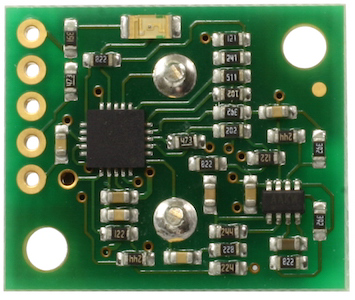
The SFR02 is a resistive sensor designed for measuring fluid levels or flow rates. Manufactured by robot-electronics, this sensor operates by varying its resistance in response to changes in the physical properties of the fluid it is monitoring. The SFR02 provides an analog output that can be easily interfaced with microcontrollers or other electronic systems, making it a versatile component for a wide range of applications.
Explore Projects Built with SFR02
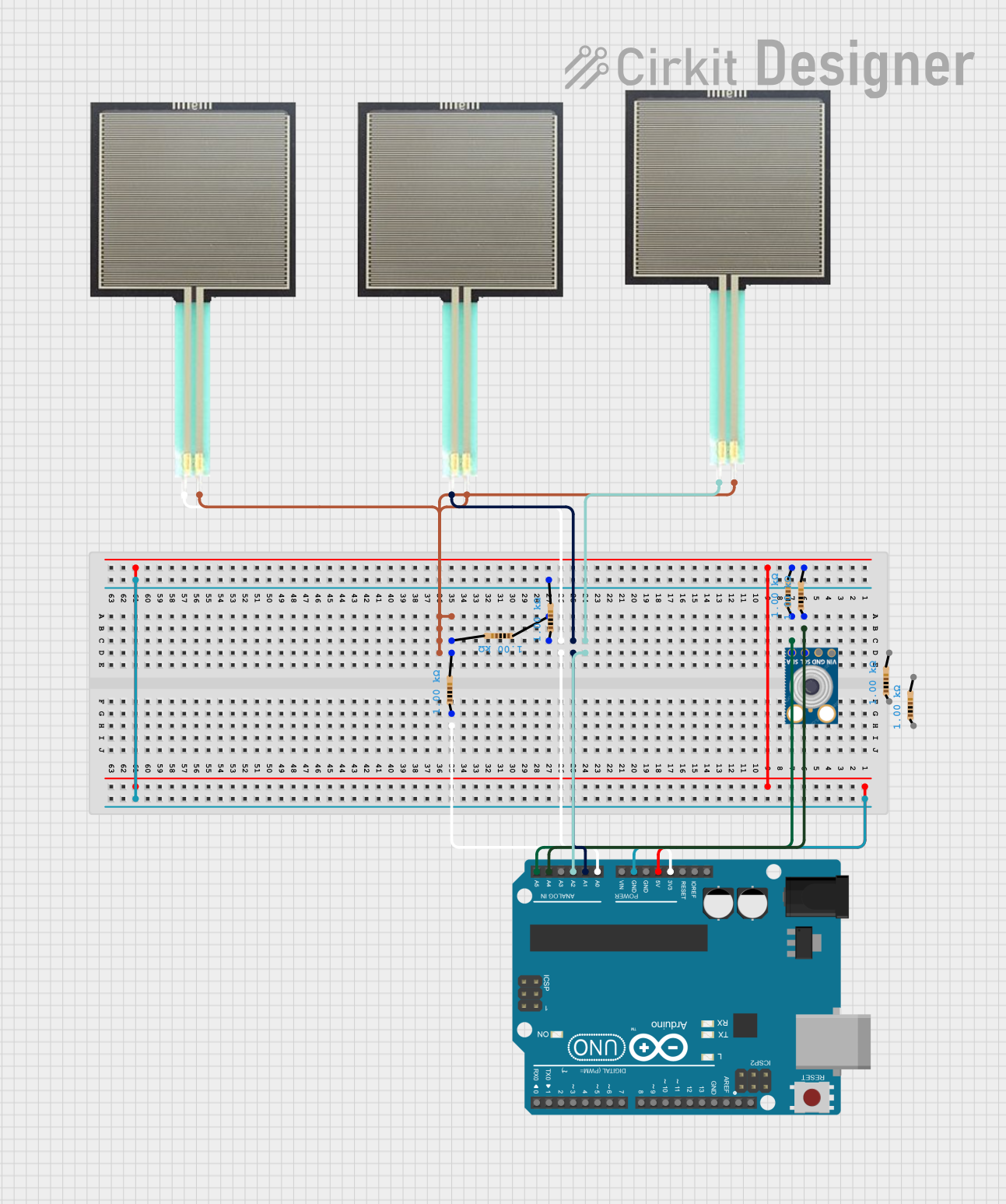

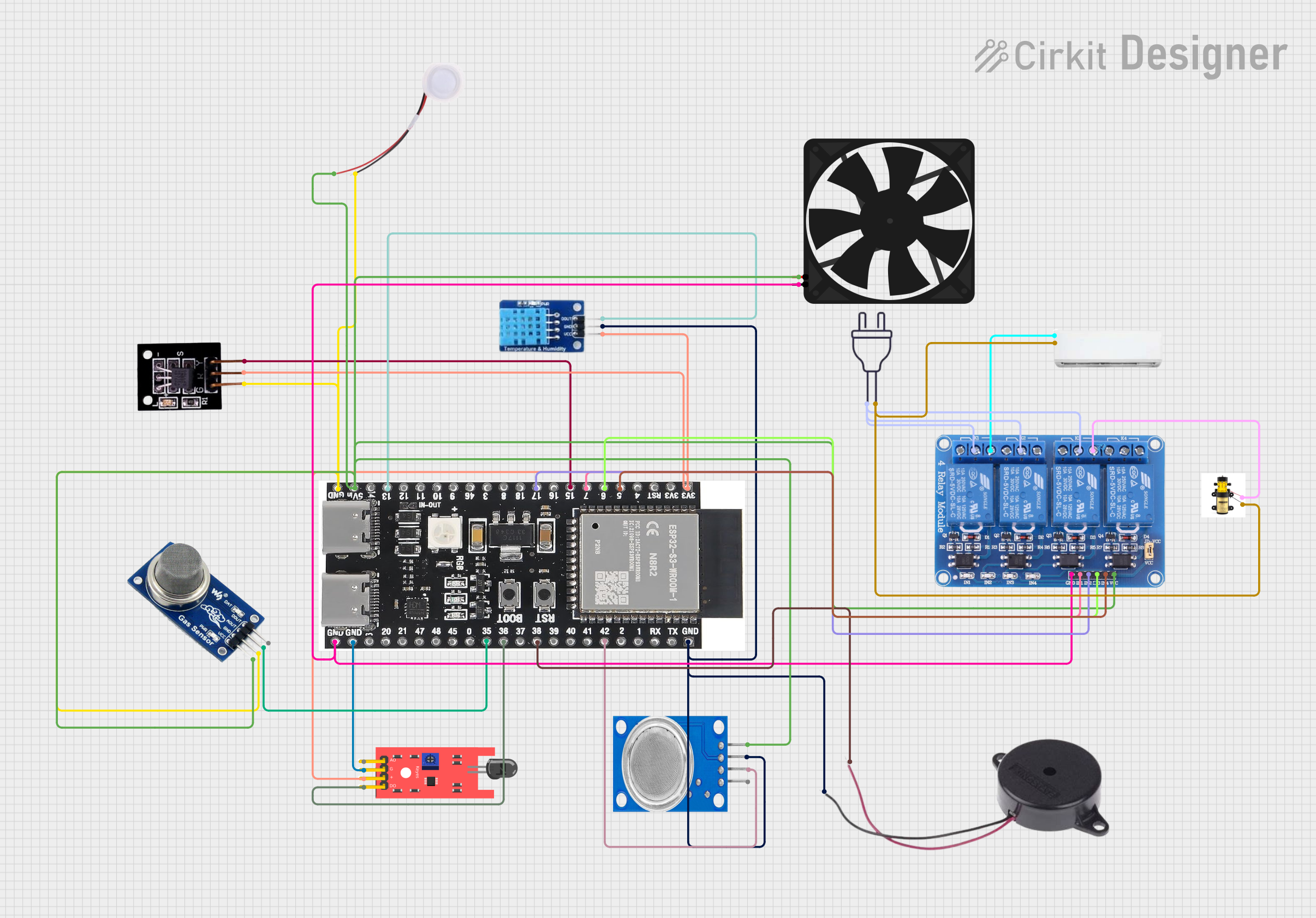
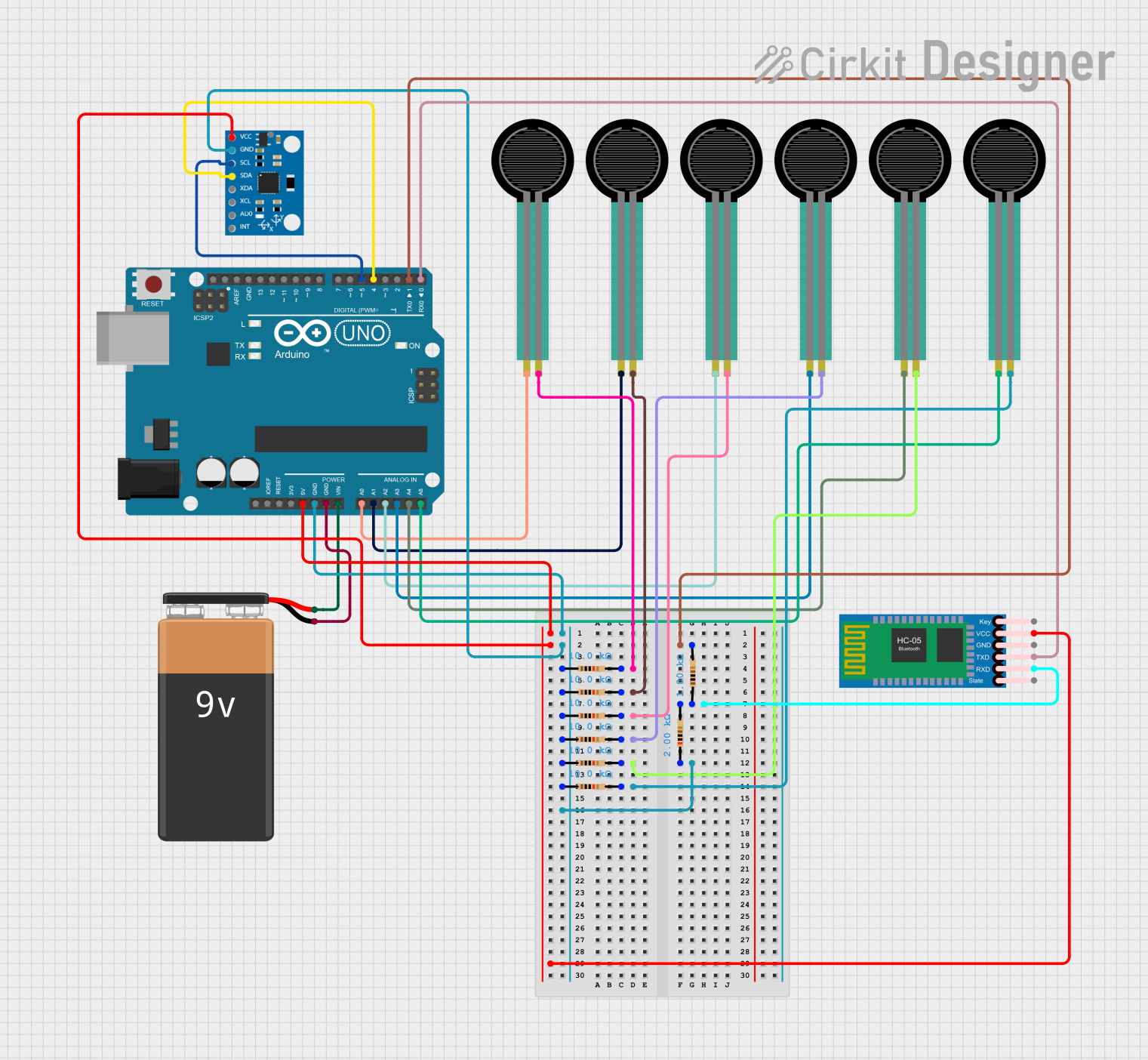
Explore Projects Built with SFR02
Common Applications
- Monitoring fluid levels in tanks or reservoirs
- Measuring flow rates in pipelines
- Industrial process control systems
- Automotive fluid monitoring (e.g., fuel or coolant levels)
- Home automation systems for water usage tracking
Technical Specifications
The following table outlines the key technical details of the SFR02 sensor:
| Parameter | Value |
|---|---|
| Manufacturer Part ID | SRF02 - I2C/Serial sensor |
| Operating Voltage | 3.3V to 5V |
| Output Type | Analog voltage |
| Measurement Range | Depends on fluid properties |
| Operating Temperature | -10°C to +85°C |
| Communication Protocol | I2C or Serial |
| Dimensions | 25mm x 20mm x 10mm |
Pin Configuration
The SFR02 sensor has a simple pinout for easy integration into circuits. The table below describes each pin:
| Pin | Name | Description |
|---|---|---|
| 1 | VCC | Power supply input (3.3V to 5V) |
| 2 | GND | Ground connection |
| 3 | SDA | I2C data line (used for communication with microcontrollers) |
| 4 | SCL | I2C clock line (used for communication with microcontrollers) |
| 5 | TX | Serial data output (used for UART communication) |
| 6 | RX | Serial data input (used for UART communication) |
Usage Instructions
How to Use the SFR02 in a Circuit
- Power the Sensor: Connect the VCC pin to a 3.3V or 5V power source and the GND pin to the ground of your circuit.
- Choose Communication Protocol: Decide whether to use I2C or Serial communication:
- For I2C, connect the SDA and SCL pins to the corresponding pins on your microcontroller.
- For Serial, connect the TX and RX pins to the UART pins on your microcontroller.
- Read the Output: Use the microcontroller to read the sensor's output. For I2C, ensure the correct address is used (default: 0x70). For Serial, configure the baud rate (default: 9600 bps).
- Process the Data: Convert the analog output or digital data into meaningful fluid level or flow rate measurements based on your application.
Important Considerations
- Fluid Compatibility: Ensure the fluid being measured is compatible with the sensor's materials to avoid damage.
- Calibration: Calibrate the sensor for the specific fluid and operating conditions to ensure accurate measurements.
- Noise Reduction: Use proper decoupling capacitors near the power pins to minimize electrical noise.
- I2C Pull-Up Resistors: If using I2C, ensure appropriate pull-up resistors (typically 4.7kΩ) are connected to the SDA and SCL lines.
Example: Using the SFR02 with Arduino UNO
Below is an example of how to interface the SFR02 with an Arduino UNO using I2C communication:
#include <Wire.h> // Include the Wire library for I2C communication

#define SFR02_ADDRESS 0x70 // Default I2C address of the SFR02 sensor

void setup() {
  Wire.begin(); // Initialize I2C communication
  Serial.begin(9600); // Initialize Serial communication for debugging
  Serial.println("SFR02 Sensor Example");
}

void loop() {
  Wire.beginTransmission(SFR02_ADDRESS); // Start communication with SFR02
  Wire.write(0x00); // Command to read sensor data
  Wire.endTransmission();

  delay(100); // Wait for the sensor to process the command

  Wire.requestFrom(SFR02_ADDRESS, 2); // Request 2 bytes of data from the sensor
  if (Wire.available() == 2) {
    int highByte = Wire.read(); // Read the high byte
    int lowByte = Wire.read();  // Read the low byte
    int sensorValue = (highByte << 8) | lowByte; // Combine the two bytes

    Serial.print("Sensor Value: ");
    Serial.println(sensorValue); // Print the sensor value to the Serial Monitor
  } else {
    Serial.println("Error: No data received from SFR02");
  }

  delay(1000); // Wait 1 second before the next reading
}
Troubleshooting and FAQs
Common Issues
No Output from the Sensor
- Cause: Incorrect wiring or power supply.
- Solution: Double-check all connections and ensure the sensor is powered with the correct voltage.
Inaccurate Measurements
- Cause: Sensor not calibrated for the specific fluid.
- Solution: Perform a calibration procedure to adjust for the fluid's properties.
I2C Communication Failure
- Cause: Missing pull-up resistors or incorrect I2C address.
- Solution: Add pull-up resistors to the SDA and SCL lines and verify the sensor's I2C address.
Serial Communication Issues
- Cause: Incorrect baud rate or wiring.
- Solution: Ensure the baud rate matches the sensor's default (9600 bps) and check TX/RX connections.
FAQs
Q: Can the SFR02 be used with fluids other than water?
A: Yes, but ensure the fluid is compatible with the sensor's materials and calibrate the sensor accordingly.
Q: What is the maximum cable length for I2C communication?
A: The maximum length depends on the pull-up resistor values and operating speed, but typically it is limited to 1 meter for standard setups.
Q: Can the SFR02 operate at 3.3V?
A: Yes, the sensor is compatible with both 3.3V and 5V power supplies.
Q: How do I change the I2C address of the SFR02?
A: Refer to the manufacturer's documentation for the specific command sequence to change the I2C address.