How to Use INA226: Examples, Pinouts, and Specs
Introduction
The INA226 is a high-side current shunt monitor with an integrated I2C interface, designed for accurate current and voltage sensing in power management applications. It features a 16-bit analog-to-digital converter (ADC) for precise measurements, making it ideal for monitoring power consumption in systems such as servers, telecommunications equipment, and battery-powered devices. The INA226 supports a wide supply voltage range, making it versatile for various applications.
Explore Projects Built with INA226


Explore Projects Built with INA226
Common Applications
- Power monitoring in servers and data centers
- Battery management systems
- DC-DC converter efficiency monitoring
- Industrial automation and control systems
- Solar power systems
Technical Specifications
Key Technical Details
- Supply Voltage (VCC): 2.7V to 5.5V
- Input Voltage Range: 0V to 36V
- Shunt Voltage Range: ±81.92mV
- Current Measurement Resolution: 16-bit
- I2C Address Range: Configurable via A0 and A1 pins
- Operating Temperature Range: -40°C to +125°C
- Communication Protocol: I2C (up to 1 MHz)
- Power Consumption: 330 µA (typical)
Pin Configuration and Descriptions
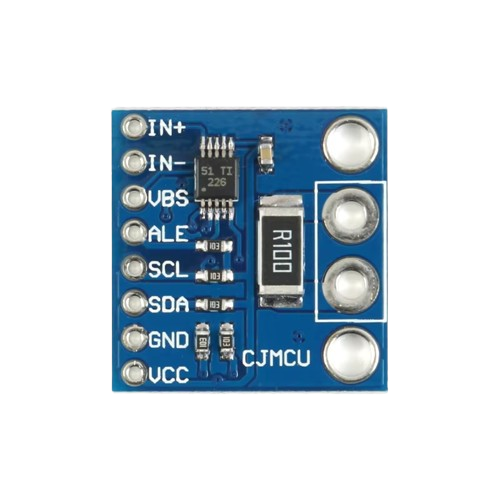
The INA226 is available in an 8-pin package. Below is the pinout and description:
| Pin Number | Pin Name | Description |
|---|---|---|
| 1 | VIN+ | Positive input for the differential voltage across the shunt resistor. |
| 2 | VIN- | Negative input for the differential voltage across the shunt resistor. |
| 3 | GND | Ground reference for the device. |
| 4 | SDA | Serial data line for I2C communication. |
| 5 | SCL | Serial clock line for I2C communication. |
| 6 | A0 | Address selection pin (LSB of I2C address). |
| 7 | A1 | Address selection pin (MSB of I2C address). |
| 8 | VCC | Power supply input (2.7V to 5.5V). |
Usage Instructions
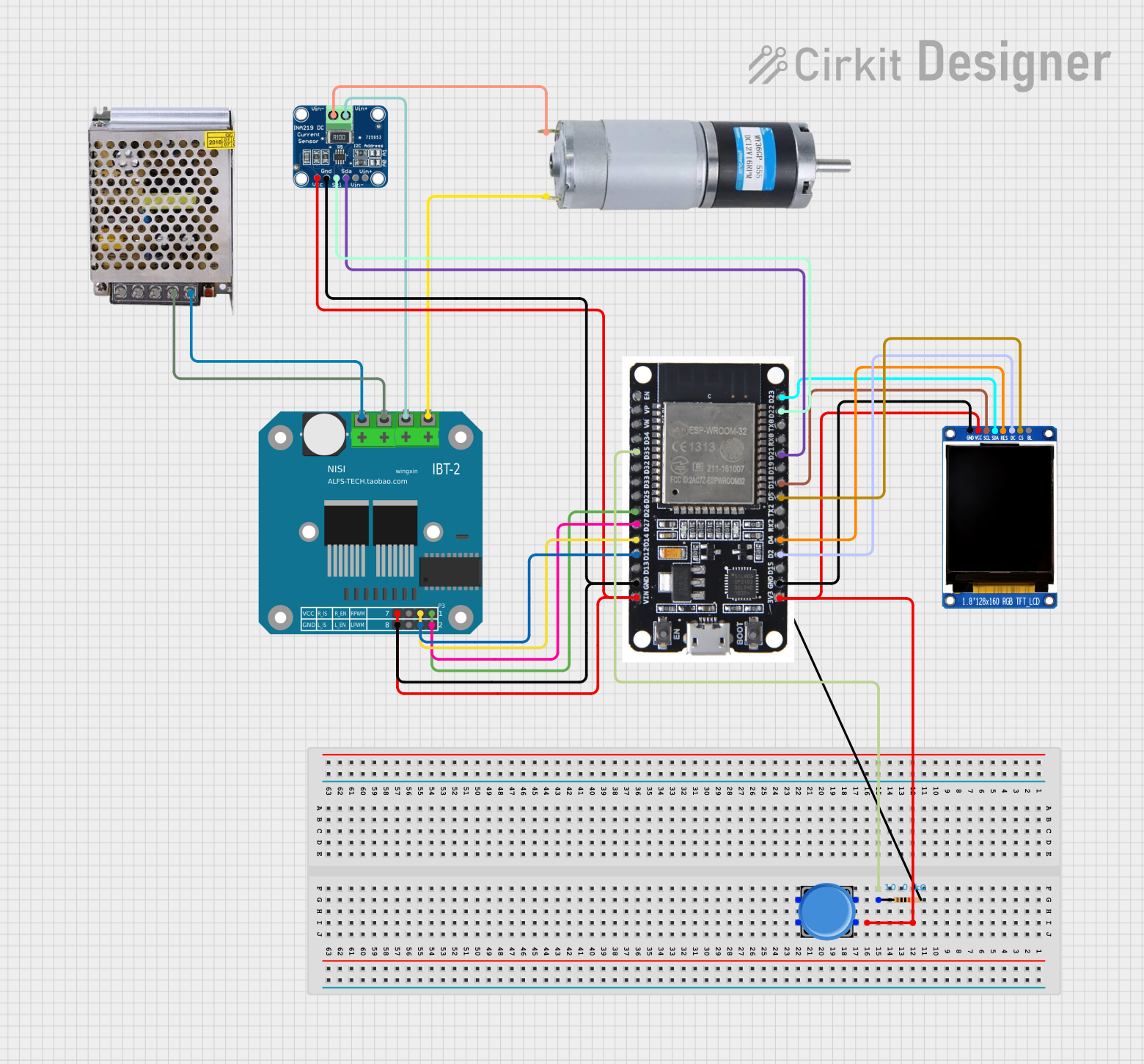
How to Use the INA226 in a Circuit
- Power Supply: Connect the VCC pin to a 2.7V to 5.5V power source and the GND pin to the ground.
- Shunt Resistor: Place a precision shunt resistor between the high-side power source and the load. Connect the VIN+ and VIN- pins across the shunt resistor.
- I2C Communication: Connect the SDA and SCL pins to the corresponding I2C lines of your microcontroller. Use pull-up resistors (typically 4.7kΩ) on these lines.
- Address Configuration: Use the A0 and A1 pins to set the I2C address of the INA226. These pins can be tied to VCC, GND, or left floating to select one of 16 possible addresses.
- Bypass Capacitor: Place a 0.1µF ceramic capacitor close to the VCC pin for decoupling.
Important Considerations
- Ensure the shunt resistor value is chosen to provide a measurable voltage drop without exceeding the ±81.92mV range.
- Avoid long traces for the shunt resistor connections to minimize noise and measurement errors.
- Use proper pull-up resistors on the I2C lines to ensure reliable communication.
- The INA226 can measure both current and bus voltage, allowing for power calculations.
Example Code for Arduino UNO
Below is an example of how to use the INA226 with an Arduino UNO to measure current and voltage:
#include <Wire.h>

// INA226 I2C address (default: 0x40 if A0 and A1 are grounded)
#define INA226_ADDRESS 0x40

// INA226 register addresses
#define REG_CONFIG 0x00
#define REG_SHUNT_VOLTAGE 0x01
#define REG_BUS_VOLTAGE 0x02

void setup() {
  Wire.begin(); // Initialize I2C communication
  Serial.begin(9600); // Initialize serial communication for debugging

  // Configure the INA226 (default configuration)
  Wire.beginTransmission(INA226_ADDRESS);
  Wire.write(REG_CONFIG); // Point to the configuration register
  Wire.write(0x45); // MSB: Set averaging and conversion times
  Wire.write(0x27); // LSB: Enable shunt and bus voltage measurements
  Wire.endTransmission();
}

void loop() {
  float shuntVoltage = readShuntVoltage(); // Read shunt voltage in mV
  float busVoltage = readBusVoltage();     // Read bus voltage in V

  Serial.print("Shunt Voltage (mV): ");
  Serial.println(shuntVoltage);
  Serial.print("Bus Voltage (V): ");
  Serial.println(busVoltage);

  delay(1000); // Wait 1 second before the next reading
}

float readShuntVoltage() {
  int16_t rawValue = readRegister(REG_SHUNT_VOLTAGE);
  return rawValue * 0.0025; // Convert to mV (LSB = 2.5µV)
}

float readBusVoltage() {
  int16_t rawValue = readRegister(REG_BUS_VOLTAGE);
  return rawValue * 0.00125; // Convert to V (LSB = 1.25mV)
}

int16_t readRegister(uint8_t reg) {
  Wire.beginTransmission(INA226_ADDRESS);
  Wire.write(reg); // Point to the desired register
  Wire.endTransmission();

  Wire.requestFrom(INA226_ADDRESS, 2); // Request 2 bytes
  int16_t value = (Wire.read() << 8) | Wire.read(); // Combine MSB and LSB
  return value;
}
Notes:
- Replace the INA226 address in the code if A0 and A1 are configured differently.
- Ensure the shunt resistor value matches the expected current range for accurate readings.
Troubleshooting and FAQs
Common Issues and Solutions
No I2C Communication:
- Ensure the SDA and SCL lines have proper pull-up resistors (4.7kΩ recommended).
- Verify the I2C address matches the configuration of the A0 and A1 pins.
- Check for loose or incorrect wiring.
Incorrect Current or Voltage Readings:
- Verify the shunt resistor value and connections.
- Ensure the shunt voltage does not exceed the ±81.92mV range.
- Minimize noise by keeping the shunt resistor traces short and using proper grounding.
Device Not Responding:
- Confirm the power supply voltage is within the 2.7V to 5.5V range.
- Check for proper bypass capacitor placement near the VCC pin.
FAQs
Q: Can the INA226 measure negative currents?
A: Yes, the INA226 can measure bidirectional currents if configured properly. Ensure the shunt voltage stays within the ±81.92mV range.
Q: What is the maximum sampling rate of the INA226?
A: The sampling rate depends on the averaging and conversion time settings. At the fastest configuration, it can achieve up to 2.1kHz.
Q: Can I use the INA226 with a 3.3V microcontroller?
A: Yes, the INA226 is compatible with 3.3V systems as long as the VCC pin is supplied with a voltage between 2.7V and 5.5V.
Q: How do I calculate power using the INA226?
A: Power can be calculated by multiplying the bus voltage and the current (derived from the shunt voltage and resistor value).