
How to Use Motor: Examples, Pinouts, and Specs
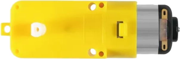
 Design with Motor in Cirkit Designer
Introduction
A motor is a device that converts electrical energy into mechanical energy, typically used to drive machinery or perform work in various applications. Motors are essential components in countless systems, ranging from household appliances to industrial machinery and robotics. They are available in various types, such as DC motors, stepper motors, and servo motors, each suited for specific tasks.
Explore Projects Built with Motor
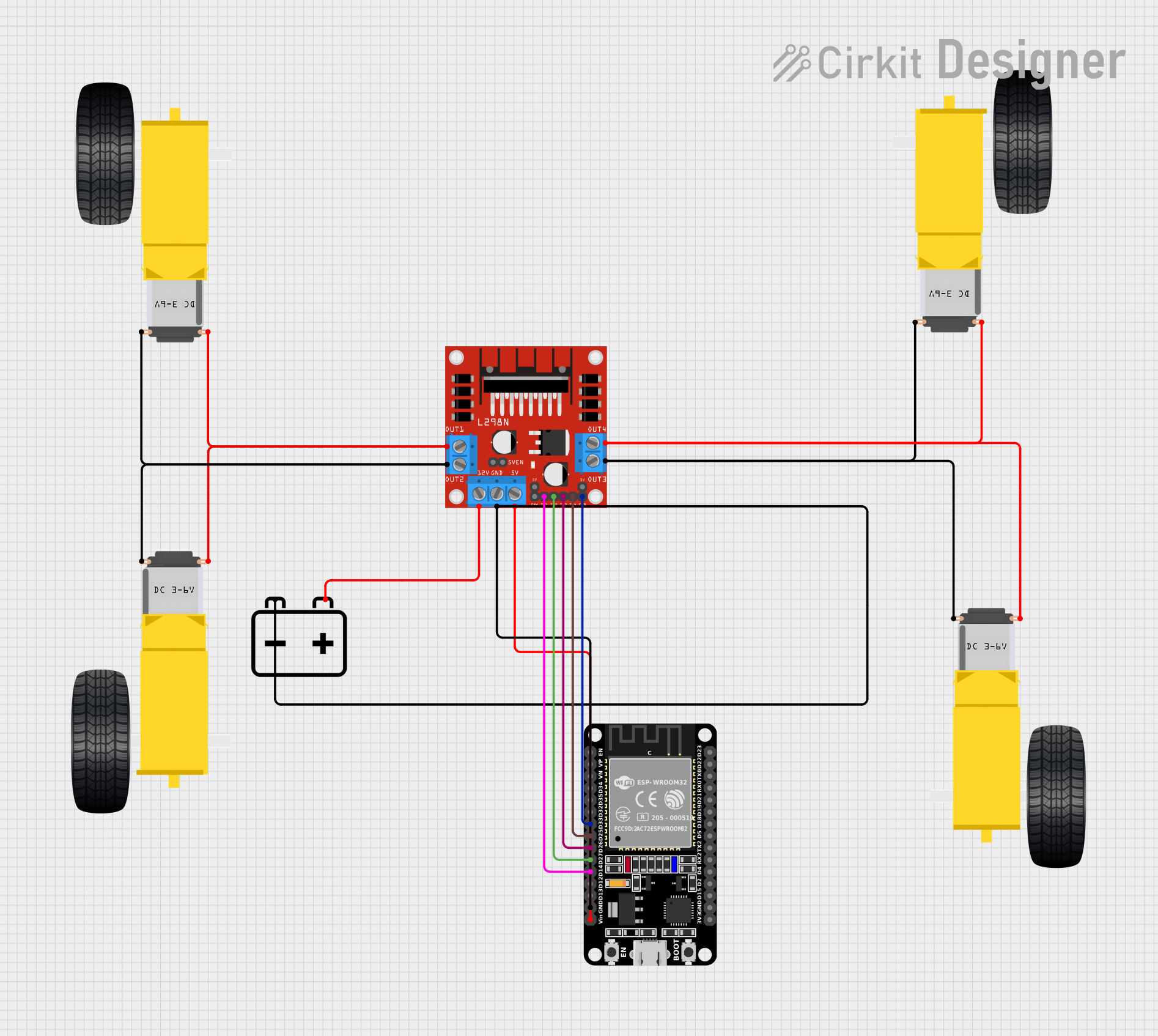 Open Project in Cirkit Designer
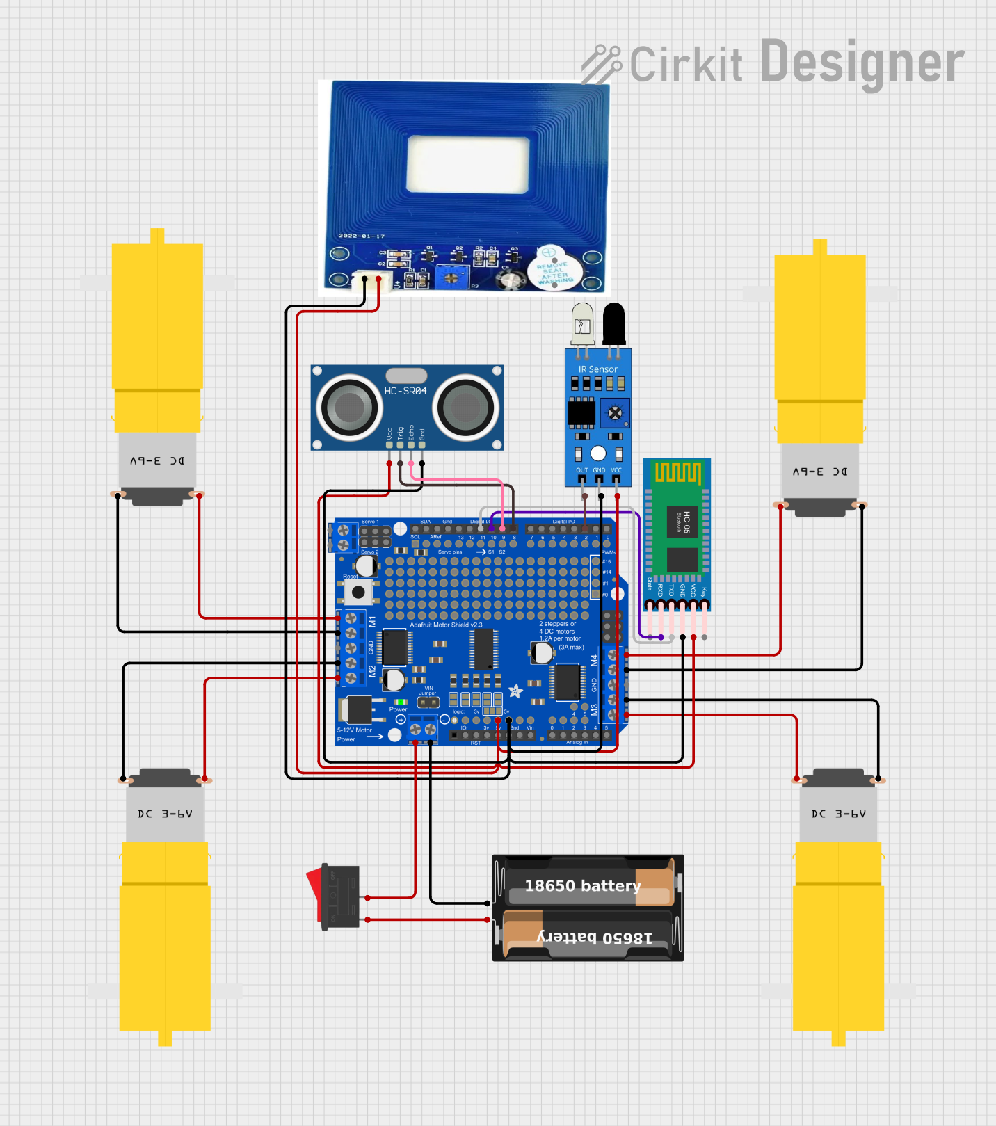 Open Project in Cirkit Designer
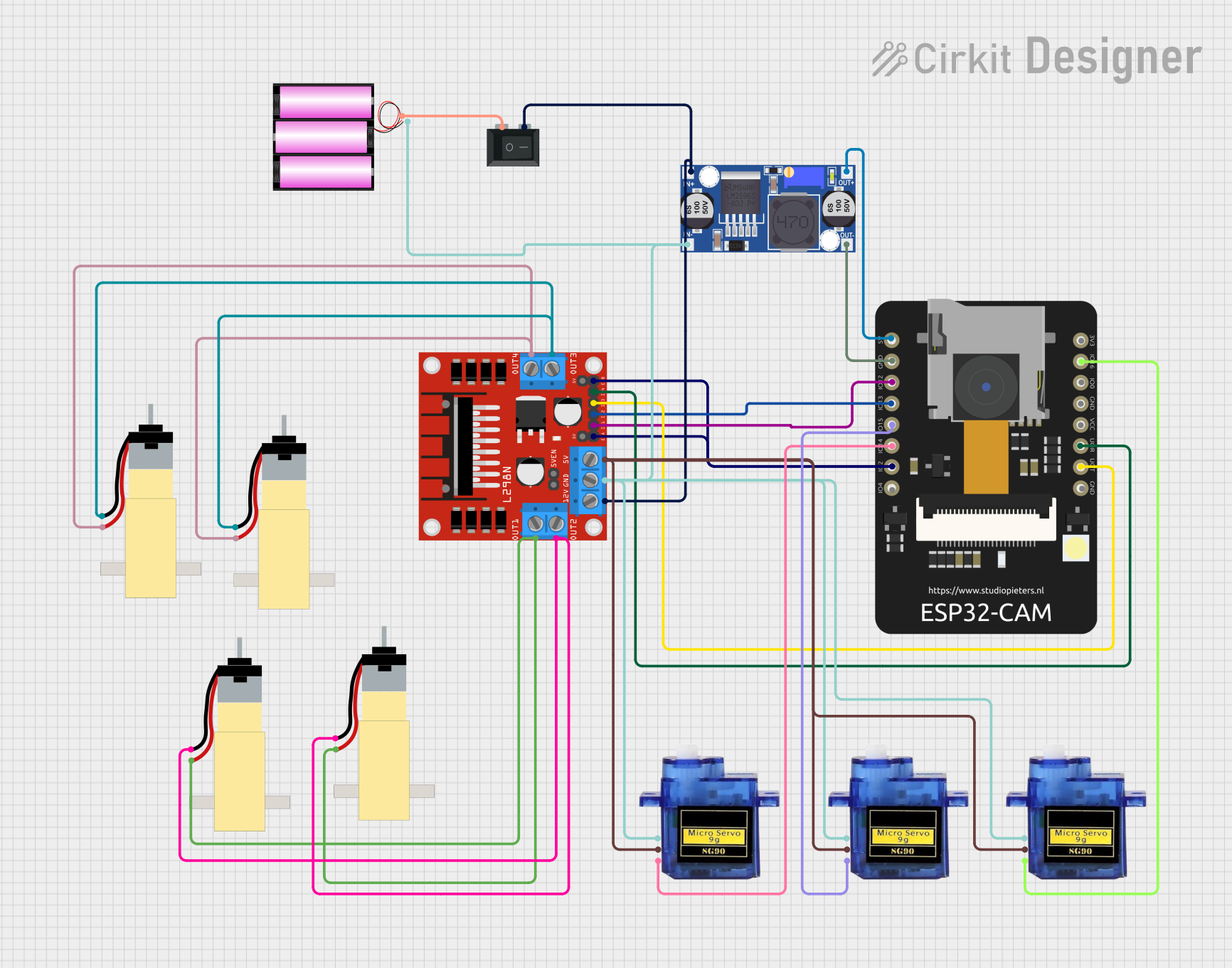 Open Project in Cirkit Designer
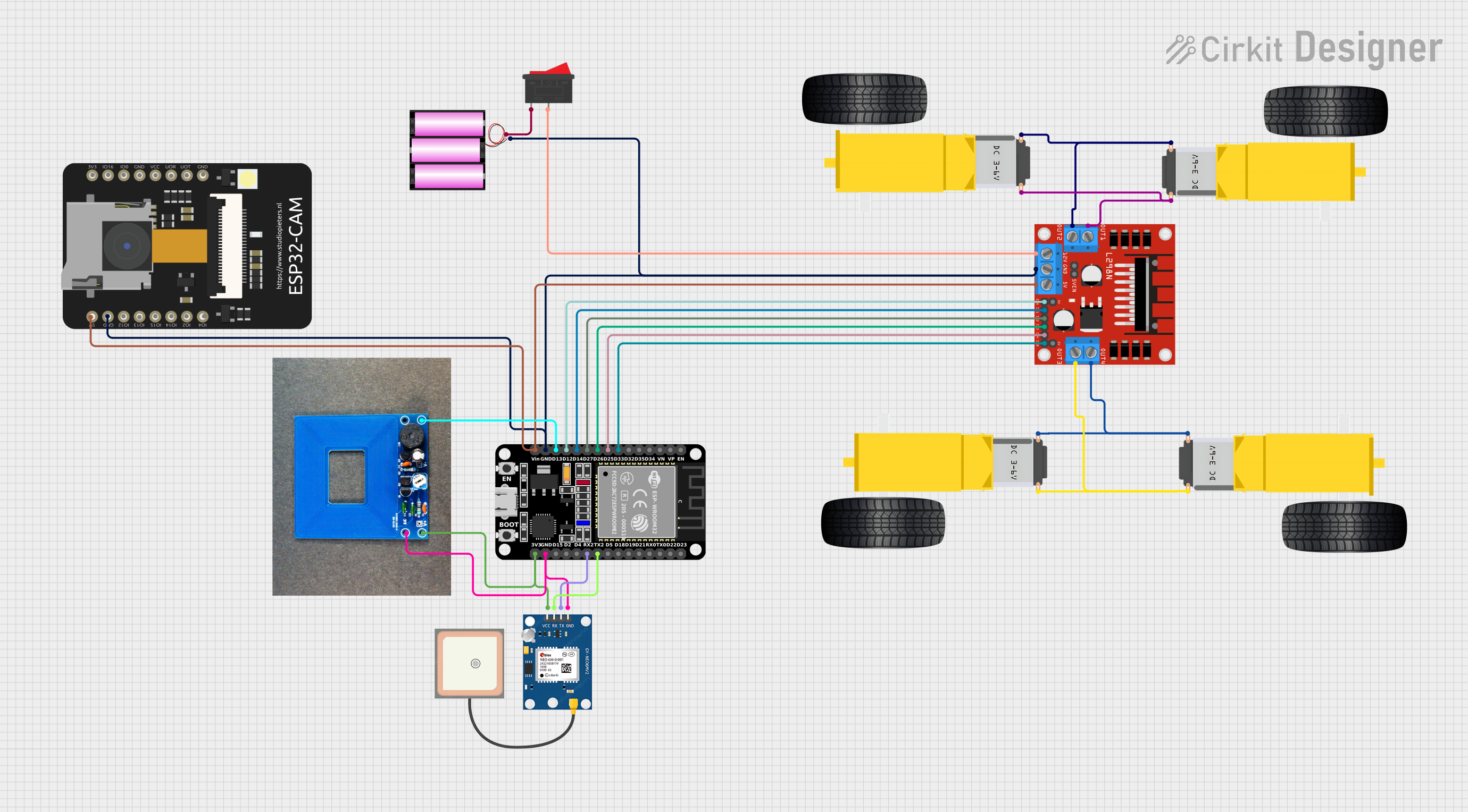 Open Project in Cirkit Designer
Explore Projects Built with Motor
Open Project in Cirkit DesignerOpen Project in Cirkit DesignerOpen Project in Cirkit DesignerOpen Project in Cirkit DesignerCommon Applications and Use Cases
- Robotics and automation systems
- Industrial machinery and conveyor belts
- Household appliances (e.g., fans, washing machines)
- Electric vehicles and drones
- Precision control systems (e.g., CNC machines, 3D printers)
Technical Specifications
The specifications of a motor vary depending on its type and intended application. Below is an example of a DC motor's general specifications:
Key Technical Details
| Parameter | Value |
|---|---|
| Operating Voltage | 3V to 12V |
| Rated Current | 100mA to 2A (depending on load) |
| Stall Current | Up to 5A |
| Speed | 1000 to 5000 RPM |
| Torque | 0.1 to 2 Nm |
| Power Output | 0.5W to 50W |
| Motor Type | Brushed DC Motor |
Pin Configuration and Descriptions
For a typical DC motor with two terminals:
| Pin Name | Description |
|---|---|
| Terminal 1 (Positive) | Connect to the positive voltage supply. |
| Terminal 2 (Negative) | Connect to ground or negative voltage. |
For motors with additional control pins (e.g., stepper or servo motors), refer to their specific datasheets for detailed pinouts.
Usage Instructions
How to Use the Motor in a Circuit
- Power Supply: Ensure the motor is powered within its specified voltage range. Use a regulated power supply or battery.
- Motor Driver: For most motors, especially DC and stepper motors, use a motor driver (e.g., L298N, L293D) to control speed and direction.
- Connections:
- Connect the motor terminals to the motor driver outputs.
- Connect the motor driver inputs to a microcontroller (e.g., Arduino UNO) for control.
- Control Signals: Use Pulse Width Modulation (PWM) to control the motor's speed and direction.
Important Considerations and Best Practices
- Current Limiting: Use a current-limiting resistor or driver to prevent overloading the motor.
- Heat Dissipation: Ensure proper ventilation or heat sinks to avoid overheating.
- Reverse Polarity: Avoid reversing the polarity unless the motor is designed for bidirectional operation.
- Load: Do not exceed the motor's rated torque or power output.
Example: Controlling a DC Motor with Arduino UNO
Below is an example code to control a DC motor using an Arduino UNO and an L298N motor driver:
// Define motor control pins
const int motorPin1 = 9; // Motor terminal 1 connected to pin 9
const int motorPin2 = 10; // Motor terminal 2 connected to pin 10
const int enablePin = 11; // Enable pin for speed control (PWM)

// Setup function
void setup() {
  pinMode(motorPin1, OUTPUT); // Set motorPin1 as output
  pinMode(motorPin2, OUTPUT); // Set motorPin2 as output
  pinMode(enablePin, OUTPUT); // Set enablePin as output
}

// Loop function
void loop() {
  // Rotate motor in one direction
  digitalWrite(motorPin1, HIGH); // Set motorPin1 HIGH
  digitalWrite(motorPin2, LOW);  // Set motorPin2 LOW
  analogWrite(enablePin, 128);   // Set speed to 50% (PWM value: 128)
  delay(2000);                   // Run for 2 seconds

  // Stop the motor
  analogWrite(enablePin, 0);     // Set speed to 0
  delay(1000);                   // Wait for 1 second

  // Rotate motor in the opposite direction
  digitalWrite(motorPin1, LOW);  // Set motorPin1 LOW
  digitalWrite(motorPin2, HIGH); // Set motorPin2 HIGH
  analogWrite(enablePin, 128);   // Set speed to 50% (PWM value: 128)
  delay(2000);                   // Run for 2 seconds

  // Stop the motor
  analogWrite(enablePin, 0);     // Set speed to 0
  delay(1000);                   // Wait for 1 second
}
Troubleshooting and FAQs
Common Issues
Motor Not Spinning:
- Check the power supply voltage and current.
- Verify connections to the motor driver and microcontroller.
- Ensure the motor driver is functioning correctly.
Motor Overheating:
- Reduce the load or torque on the motor.
- Check for proper ventilation or add a heat sink.
Erratic Motor Behavior:
- Verify the PWM signal from the microcontroller.
- Check for loose or faulty connections.
Noisy Operation:
- Add capacitors across the motor terminals to reduce electrical noise.
- Ensure the motor is securely mounted to minimize vibrations.
FAQs
Q: Can I connect a motor directly to a microcontroller?
A: No, most microcontrollers cannot supply the required current to drive a motor. Use a motor driver or transistor circuit.
Q: How do I reverse the motor's direction?
A: Swap the polarity of the motor terminals or use an H-bridge motor driver to control direction programmatically.
Q: What is the difference between a DC motor and a stepper motor?
A: A DC motor provides continuous rotation, while a stepper motor moves in discrete steps, offering precise position control.
Q: Can I use a single power supply for both the motor and microcontroller?
A: Yes, but ensure the power supply can handle the combined current requirements and use proper decoupling to avoid noise issues.