How to Use Time Delay Relay: Examples, Pinouts, and Specs
Introduction
A Time Delay Relay is an electromechanical or solid-state device that opens or closes its contacts after a preset time delay. This component is widely used in applications requiring time-based control, such as industrial automation, motor control, lighting systems, and HVAC systems. By introducing a delay in the operation of a circuit, Time Delay Relays help ensure proper sequencing, prevent equipment damage, and improve system efficiency.
Common applications include:
- Delayed motor start to prevent inrush current.
- Sequential control of machinery in industrial processes.
- Automatic lighting systems with delayed turn-off.
- Safety systems requiring timed responses.
Explore Projects Built with Time Delay Relay


Explore Projects Built with Time Delay Relay
Technical Specifications
Below are the general technical specifications for a typical Time Delay Relay. Note that specific models may vary, so always refer to the datasheet of your relay.
| Parameter | Value |
|---|---|
| Operating Voltage | 12V DC, 24V DC, or 110-240V AC |
| Contact Type | SPDT (Single Pole Double Throw) or DPDT (Double Pole Double Throw) |
| Contact Rating | 10A at 250V AC / 10A at 30V DC |
| Time Delay Range | 0.1 seconds to 10 minutes (adjustable) |
| Timing Adjustment | Potentiometer or DIP switches |
| Trigger Input | Voltage signal or mechanical switch |
| Operating Temperature | -20°C to 60°C |
| Mounting Type | DIN rail or panel mount |
Pin Configuration and Descriptions
The pin configuration of a Time Delay Relay typically includes input, output, and control pins. Below is an example of a 5-pin Time Delay Relay:
| Pin Number | Name | Description |
|---|---|---|
| 1 | Input (+) | Positive voltage supply (e.g., 12V DC or 24V DC) |
| 2 | Input (-) | Ground connection |
| 3 | Common (COM) | Common terminal for the relay contacts |
| 4 | Normally Open (NO) | Contact that closes after the time delay |
| 5 | Normally Closed (NC) | Contact that opens after the time delay |
Usage Instructions
How to Use the Component in a Circuit
- Power the Relay: Connect the input pins (e.g., Pin 1 and Pin 2) to the appropriate power supply. Ensure the voltage matches the relay's operating voltage.
- Set the Time Delay: Adjust the potentiometer or DIP switches on the relay to set the desired delay time.
- Connect the Load:
- Connect the load to the Common (COM) pin and either the Normally Open (NO) or Normally Closed (NC) pin, depending on the desired operation.
- For example, use the NO pin if you want the load to activate after the delay.
- Trigger the Relay: Apply a trigger signal (e.g., a voltage pulse or switch activation) to start the timing sequence.
- Observe Operation: After the preset delay, the relay will switch its contacts, activating or deactivating the connected load.
Important Considerations and Best Practices
- Voltage Compatibility: Ensure the relay's operating voltage matches your power supply.
- Contact Ratings: Do not exceed the relay's contact rating to avoid damage.
- Isolation: Use optoisolators or separate power supplies if the relay is controlling high-voltage loads.
- Debouncing: If using a mechanical switch as a trigger, consider adding a debouncing circuit to prevent false triggering.
- Heat Dissipation: Ensure proper ventilation or heat sinking if the relay operates continuously for long periods.
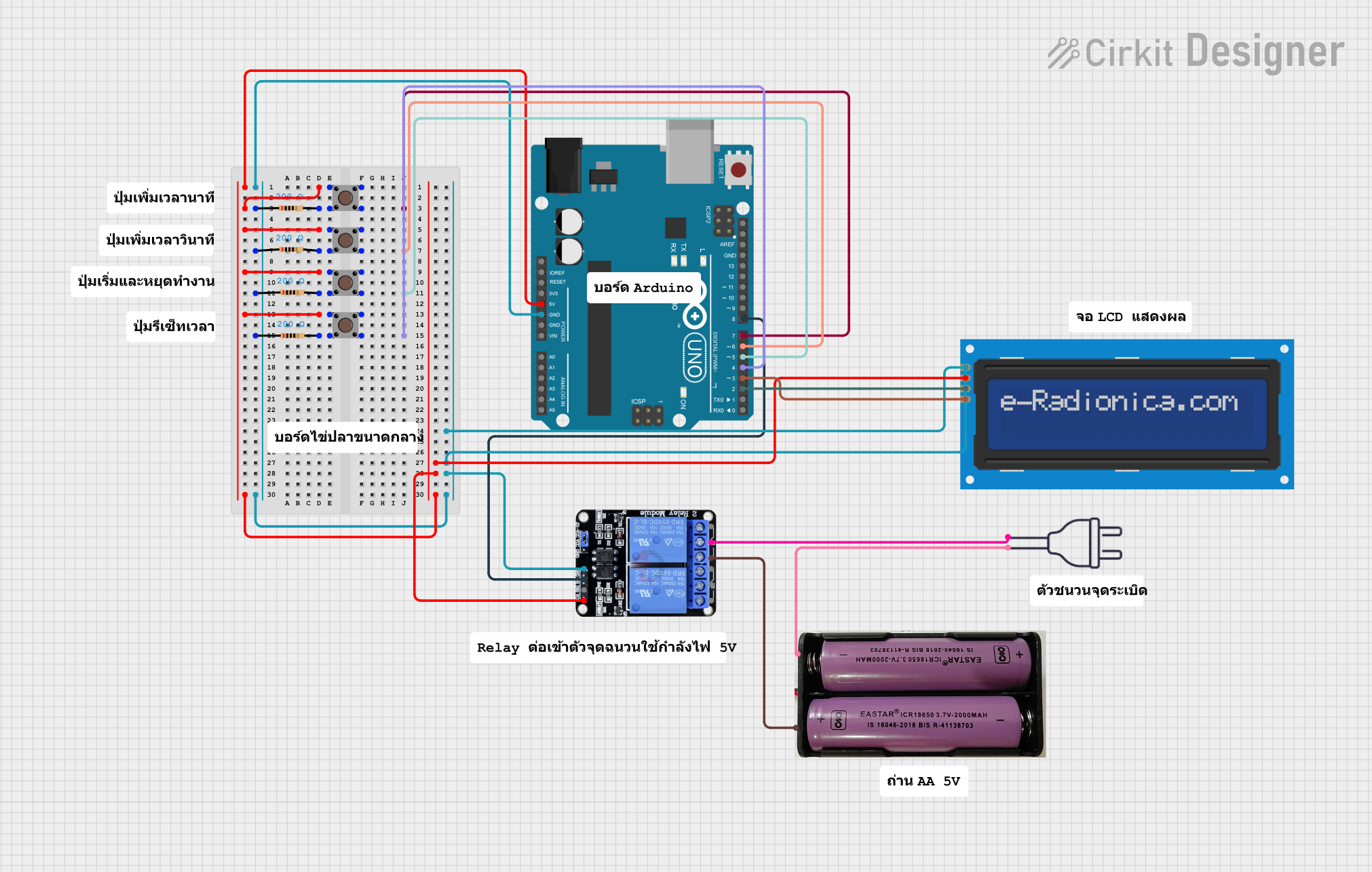
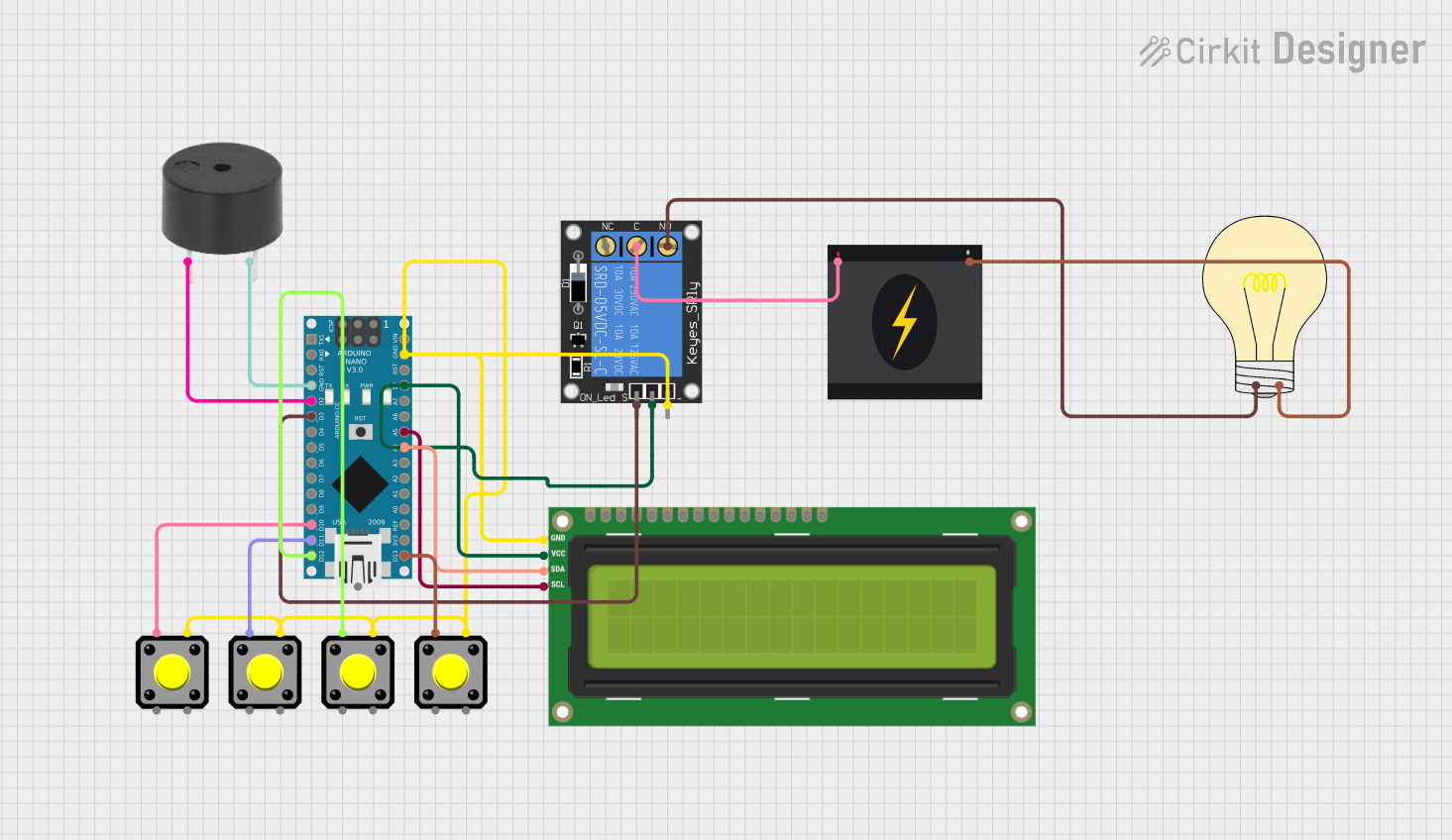
Example: Using a Time Delay Relay with Arduino UNO
Below is an example of how to use a Time Delay Relay with an Arduino UNO to control a load after a 5-second delay.
Circuit Connections
- Connect the relay's input pins to a 12V DC power supply.
- Connect the relay's trigger pin to Arduino digital pin 7.
- Connect the relay's COM pin to one terminal of the load.
- Connect the NO pin to the other terminal of the load.
- Connect the load's power supply as required.
Arduino Code
// Time Delay Relay Example with Arduino UNO
// This code triggers a Time Delay Relay after a 5-second delay.

const int relayPin = 7; // Pin connected to the relay trigger input

void setup() {
  pinMode(relayPin, OUTPUT); // Set relayPin as an output
  digitalWrite(relayPin, LOW); // Ensure relay is off at startup
}

void loop() {
  delay(5000); // Wait for 5 seconds
  digitalWrite(relayPin, HIGH); // Trigger the relay
  delay(10000); // Keep the relay on for 10 seconds
  digitalWrite(relayPin, LOW); // Turn off the relay
  delay(5000); // Wait for 5 seconds before repeating
}
Troubleshooting and FAQs
Common Issues and Solutions
Relay Does Not Activate:
- Check the power supply voltage and ensure it matches the relay's operating voltage.
- Verify the trigger signal is being applied correctly.
- Inspect the wiring for loose or incorrect connections.
Load Does Not Operate:
- Ensure the load is connected to the correct relay contacts (COM and NO/NC).
- Check the load's power supply and ensure it is functioning properly.
- Verify the relay's contact rating is sufficient for the load.
Relay Activates Erratically:
- Add a debouncing circuit if using a mechanical switch as a trigger.
- Check for electrical noise or interference in the circuit.
Time Delay is Incorrect:
- Recheck the potentiometer or DIP switch settings.
- Ensure the relay is not faulty by testing with a different unit.
FAQs
Q: Can I use a Time Delay Relay with an AC load?
A: Yes, as long as the relay's contact rating supports the AC voltage and current of the load.
Q: How precise is the timing of a Time Delay Relay?
A: The timing precision depends on the relay's design. Mechanical relays may have slight variations, while solid-state relays offer higher accuracy.
Q: Can I use a Time Delay Relay for both delay-on and delay-off operations?
A: Some relays support both modes, but you may need to configure the relay or use a specific model designed for dual functionality.
Q: What happens if I exceed the relay's contact rating?
A: Exceeding the contact rating can cause overheating, arcing, or permanent damage to the relay. Always use a relay with a suitable rating for your application.