Cirkit Designer LogoCirkit DesignerYour all-in-one circuit design IDE Launch Cirkit Designer App

How to Use Digital thermostat relay with NTC-thermistor: Examples, Pinouts, and Specs

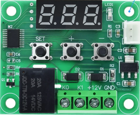
Image of Digital thermostat relay with NTC-thermistorDesign with Digital thermostat relay with NTC-thermistor in Cirkit Designer

Introduction

The Digital Thermostat Relay with NTC-Thermistor is a versatile electronic component designed for precise temperature regulation. It uses a Negative Temperature Coefficient (NTC) thermistor to measure temperature and activates a relay to control heating or cooling systems. This component is widely used in applications requiring automated temperature control, such as HVAC systems, incubators, aquariums, and industrial equipment.

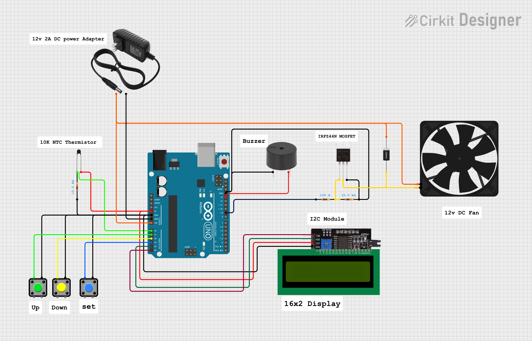
Explore Projects Built with Digital thermostat relay with NTC-thermistor

Use Cirkit Designer to design, explore, and prototype these projects online. Some projects support real-time simulation. Click "Open Project" to start designing instantly!

Common Applications and Use Cases

Technical Specifications

Key Technical Details

Pin Configuration and Descriptions

Pin Name Description
VCC Positive power supply input (12V DC).
GND Ground connection.
NTC Input for the NTC thermistor sensor.
NO Normally Open relay terminal. Connect to the load for switching.
COM Common relay terminal.
NC Normally Closed relay terminal. Connect to the load for normally closed state.

Usage Instructions

How to Use the Component in a Circuit

  1. Power Supply: Connect the VCC pin to a 12V DC power source and the GND pin to ground.
  2. Sensor Connection: Attach the NTC thermistor to the NTC input. Place the thermistor in the environment where temperature needs to be measured.
  3. Relay Connection:
    • For heating systems: Connect the load (e.g., heater) between the NO and COM terminals.
    • For cooling systems: Connect the load (e.g., fan or cooler) between the NC and COM terminals.
  4. Configuration: Use the onboard buttons to set the desired temperature, hysteresis, and control mode (heating or cooling).
  5. Operation: Once powered, the thermostat will monitor the temperature and activate the relay to maintain the set temperature range.

Important Considerations and Best Practices

Example: Connecting to an Arduino UNO

The thermostat relay can be controlled or monitored using an Arduino UNO. Below is an example code to read the relay state and display it on the serial monitor.

// Example code to monitor the relay state of a digital thermostat
// connected to an Arduino UNO. Ensure the relay's COM pin is connected
// to the Arduino's digital pin (e.g., pin 7).

const int relayPin = 7; // Pin connected to the relay's COM terminal

void setup() {
  pinMode(relayPin, INPUT); // Set the relay pin as input
  Serial.begin(9600);       // Initialize serial communication
}

void loop() {
  int relayState = digitalRead(relayPin); // Read the relay state
  if (relayState == HIGH) {
    Serial.println("Relay is ON (Load is active).");
  } else {
    Serial.println("Relay is OFF (Load is inactive).");
  }
  delay(1000); // Wait for 1 second before the next reading
}

Troubleshooting and FAQs

Common Issues and Solutions

  1. Thermostat Not Powering On:

    • Cause: Incorrect power supply or loose connections.
    • Solution: Verify the power supply voltage (12V DC) and check all connections.
  2. Temperature Readings Are Inaccurate:

    • Cause: Faulty or improperly placed NTC thermistor.
    • Solution: Ensure the thermistor is securely connected and placed in the correct location. Replace the thermistor if damaged.
  3. Relay Not Switching:

    • Cause: Load exceeds the relay's current/voltage rating or incorrect wiring.
    • Solution: Check the load specifications and ensure proper wiring. Use a relay with higher ratings if necessary.
  4. Hysteresis Not Working as Expected:

    • Cause: Incorrect hysteresis settings.
    • Solution: Reconfigure the hysteresis value using the onboard buttons.

FAQs